Download
1 / 59
600 likes | 636 Views
Explore the evolution of PF fusion devices, from numerical experiments to high-temperature plasma production and radiation emission. Learn about the innovative methods driving this technology forward, including the plasma focus mechanism. Discover the applications of PF devices beyond fusion, such as SXR Lithography and materials modification. Witness the potential for plasma focus devices in diverse fields like radiation safety, baggage inspection, and plasma propulsion. Delve into the intricate workings and future prospects of these cutting-edge devices.

E N D
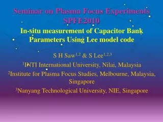
Plasma Focus Fusion Devices S Lee & S H Saw Institute for Plasma Focus Studies INTI University College, Malaysia Gazi University Technical Education Faculty, Ankara 2 October 2009 10 am
Plan of Talk • Description of PF fusion devices- from small to big • Experiments and results • Numerical Experiments confirm deterioration of scaling laws • New ideas needed- beyond present saturation.
When matter is heated to high temperatures: • It ionizes and becomes a plasma; emitting radiation • Generally, the higher the temperature T and density n, the more intense the radiation • Depending on heating mechanisms, beams of ions and electrons may also be emitted • In Deuterium, nuclear fusion may take place, if n & T are high enough; neutrons are also emitted. • Typically T> several million K; & compressed n: above atmospheric density.
One method: electrical discharge through gases. Heated gas expands, lowering the density; making it difficult to heat further. Necessary to compress whilst heating, to achieve sufficiently intense conditions. Electrical discharge between two electrodes produces azimuthal magnetic field which interacts with column of current; giving rise to a self compression force which tends to constrict (or pinch) the column. To ‘pinch’ a column of gas to atmospheric density at T~ 1 million K, a rather large pressure has to be exerted by the pinching magnetic field. Electric current of hundreds of kA required, even for column of radius of say 1mm. Dynamic pinching process requires current to rise very rapidly, typically in under 0.1 microsec in order to have a sufficiently hot and dense pinch. Super-fast, super-dense pinch; requires special MA fast-rise (nanosec) pulsed-lines; Disadvantages: conversion losses and cost of the high technology pulse-shaping line, additional to the capacitor.
Superior method for super-dense-hot pinch: plasma focus (PF) • The PF produces superior densities and temperatures. • 2-Phase mechanism of plasma production does away with the extra layer of technology required by the expensive and inefficient pulse-shaping line. • A simple capacitor discharge is sufficient to power the plasma focus.
THE PLASMA FOCUS • The PF is divided into two sections. • Pre-pinch (axial) section: Delays the pinch until the capacitor discharge approaches maximum current. • The pinch starts & occurs at top of the current pulse. • Equivalent to driving the pinch with a super-fast rising current; without necessitating the fast line technology. • The intensity which is achieved is superior to even the super fast pinch.
Two Phases of the Plasma Focus Axial Phase Radial Phase
HV 30 mF, 15 kV The Plasma Dynamics in Focus Radial Phase Axial Acceleration Phase Inverse Pinch Phase
Plasma Focus Devices in Singapore The UNU/ICTP PFF (UnitedNationsUniversity/International Centre for Theoretical Physics Plasma Focus Facility) 15 kV, 3kJ single-shot, portable; 170kA 3J SXR per shot (neon) 108 neutrons/ shot (in D2) 1016 neutrons/s (estimated) (This device is also in operation in Malaysia, Thailand, India, Pakistan, Egypt, Zimbabwe) 1m
NX2-Plasma SXR Source • 11.5kV, 2 kJ • 16 shots /sec; 400 kA • 20J SXR/shot (neon) • 109 neutrons/shot
300J PF:(2.4 µF, T/4 ~ 400 ns, 15 kV, 270 J, total mass ~25 kg) neutron yield: (1.2±0.2) × 106 neutrons/shot at ~80 kA peak current; compact, portable, quasi-continuous pulsed neutron fusion source, a 'fast miniature plasma focus device'
High Power Radiation from PF • powerful bursts of x-rays, ion beams, REB’s, & EM radiation (>10 gigaW) • Intense radiation burst, extremely high powers • E.g. SXR emission peaks at 109 W over ns • In deuterium, fusion neutrons also emitted
Applications (non-fusion) SXR Lithography • As linewidths in microelectronics reduces towards 0.1 microns, SXR Lithography is set to replace optical lithography. • Baseline requirements, point SXR source • less than 1 mm source diameter • wavelength range of 0.8-1.4 nm • from industrial throughput considerations, output powers in excess of 1 kW (into 4p)
3 1 2 5 6 4 7 8 9 10 PF SXR Schematic for Microlithography • 1 - anode • 2 - cathode • 3 - SXR point source • 4 - x-rays • 5 - electron beam • deflection magnets • 6 - shock wave shield • 7 - Be window • 8 - x-ray mask • 9 - x-ray resist • 10 - substrate
Lines transferred using NX2 SXR X-ray masks in Ni & Au SEM Pictures of transfers in AZPN114 using NX2 SXR
Other Applications –non fusion Materials modification using Plasma Focus Ion Beam Forplasma processing of thin film materials on different substrates with different phase changes.
Other Applications • Studies on Radiation safety & pulsed neutron activation • Baggage inspection using pulsed neutrons • Plasma propulsion • Pulsed neutron source for on-site e.g. oil well inspection • High speed imaging using combined x-rays & neutrons • Broad-spectrum, improved contrast x-ray tomography • Simulation of radiation from nuclear explosion
Important general results fromDecades of research measuring all aspects of the plasma focus: -imaging for dynamics -interferometry for densities -spectroscopy for temperatures -neutrons, radiation yields, MeV particles Result: commonly accepted picture today that mechanisms within the focus pinch : - micro- & MHD instabilities -acceleration by turbulence - 'anomalous' plasma resistance are important to plasma focus behaviour, and neutron yields are non-thermonuclear in origin Summarised in: Bernard A, Bruzzone H, Choi P, Chuaqui H, Gribkov V, Herrera J, Hirano K, Krejci A, Lee S, Luo C 1998 “Scientific status of plasma focus research” J Moscow Physical Society 8 93-170
Most important general property of the Plasma Focus Energy density constancy The smallest sub-kJ plasma focus and the largest MJ plasma focus have practically: - the same energy density (per unit mass) - the same temperatures, - the same speeds. Plasma volumes & lifetimes; increase with anode radius ‘a’ pinch radius ~a pinch length ~a pinch lifetime ~a radius a~ current I Derived from model scaling, based on observation of constancy of speed factor across plasma focus devices
One of most exciting properties of plasma focus is its neutron yield Yn • Early experiments show: Yn~E02 • Prospect was raised in those early research years that, breakeven could be attained at ~100 MJ. • However quickly shown that as E0 approaches 1 MJ, a neutron saturation effect was observed; in other words, Yn does not increase much more as E0 was progressively raised above several hundred kJ • Question:Is there a fundamental reason for Yn saturation? • In Part 2 of this paper we will identify one simple fundamental factor for Yn saturation; after we discuss the use of modelling for providing reference points for diagnostics.
Modern Status Now PF facilities (small to big) operate in Poland (PF-1000 and PF-6 in IPPLM, PF-360), Argentina, China, Chile, Great Britain, India, Iran, Japan, Mexico, Korea, Malaysia, Pakistan, Romania, Singapore, Thailand, Turkey, USA, Zimbabwe etc. This direction is also traditional for Russia: Kurchatov Institute (PFE, 180 kJ and biggest in the world facility PF-3, 2.8 MJ), Lebedev Institute (“Tulip”, PF-4), MEPhI, Sarov, ITEF (PF-10)- from V.I. Krauz
1997 ICDMP (International Centre for Dense Magnetised Plasmas) Warsaw-now operates one of biggest plasma focus in the world, the PF1000
PF-1000, IPPLM, Warsaw • Vacuum chamber ~ 3.8 m3 • = 1.4 m, L = 2.5 m • Anode diameter is 226 mm • Cathode diameter is400 mm • Cathode consists of 24 rods • (32 mm in diameter) • Anode length is 560 mm • Insulator length is 113 mm Charging voltage - U0 = 20 - 40 kV, Bank capacitance - C0 = 1.332 mF, Bank energy - E0 = 266 - 1064 kJ, Nominal inductance - L0 = 15 nH, Quarter discharge time - T/4 = 6s, Short-circuit current – ISC = 12 MA, Characteristic resistance - R0 = 2.6 m, Main goal – studies on neutron production at high energy input Presented by M.Scholz, IPPLM
An interesting trend-Numerical Experiments using Lee model code to benchmark Diagnostics Once the computed current trace is fitted to the Measured Current, the numerical experiment and the laboratory experiment are mass and energy compatible; & computed properties are realistic. Model is an Universal Numerical Machine
Computed Properties of the PF1000: Currents, tube voltage, trajectories, speeds, energy distributions, temperatures, densities, SXR power and neutron yield
Plasma Focus PF-3 • Filippov’s-type • Anode Diameter = 1 m • Chamber Diameter=2,5 m • Cathode - 48 rods; diameter = 115 cm Distance between anode and upper = 10 cm • Height of the insulator = 14 cm • Maximal energy (Cmax=9,2 mF, Vmax=25 kV) is 2,8 MJ • Short-circuit current =19 MA • Current on the load - up to 4 MA at 1MJ Built in 1983 Main direction of activity - Search of new ways of PF performance and applications. E.g. use PF as a driver for magnetic compression of liners
PF-3 Experimental Setup- with plasma producing substances Experiments with various plasma-producing substances & various filling gases were recently the main content of activities at the PF-3 facility Vacuum lock developed for delivery of liners to compression zone. 1 – anode; 2 – cathode; 3 – insulator; 4 – plasma current sheath; 5 – anode insertion; 6 – suspension ware; 7 – liner; 8 – loading unit with a vacuum lock; 9, 10 – diagnostics ports; PF discharge chamber
Experimental set-up– Dust Target Dust target produced at system axis as a freely-falling flow of fine-dispersed (2 - 50 mm) powder of Al2O3 1 – anode; 2 – cathode; 3 – insulator; 4 – central anode insert; 5 – plasma-current sheath; 6 – pinch; 7 – dust column; 8 – vacuum lock; 9 – shaping drifting tube; 10 – tank with powder; 11 – electromagnet; 12, 13 – diagnostic ports
Frame Camera Pictures of Pinch FormationFrame exposure – 12 ns, time delay between frames – 150 ns Discharge in neon without dust -300 ns -150ns 0 ns 150 ns Discharge in neon with dust 500 ns 650 ns 800 ns 950 ns
KPF-4 (“PHOENIX”), SPhTI, SukhumYu .V.Matveev Capacitive storage (left) & chamber with current collector (right) Wmax= 1.8 MJ, Vmax=50 kV, Mather-type outer electrode – 300 mm in diameter (36 cooper rods, 10 mm in diameter) inner electrode (anode) – 182 mm in diameter, 326 mm in length insulator – alumina, 128 mm in diameter, 50-100 mm in length Discharge dynamics studied up to 700 kJ and discharge currents 3-3.5 МА Main goal – development of powerful neutron and X-ray source for applications. (E.A.Andreeshchev, D.A.Voitenko, V.I.Krauz, A.I.Markolia, Yu.V.Matveev, N.G.Reshetnyak, E.Yu.Khautiev, 33 Zvenigorod Conf. on Plasma Phys. and Nuclear Fus., February 13-17, 2006, Zvenigorod, Russia)
Plasma Focus formedical application programme (PFMA_1) This program is developed in Italy in cooperation of Ferrara and Bologna Universities Today's status is: • Preliminary campaign with a relatively small Plasma Focus device (7 kJ, 17 kV, 600 kA maximum) confirmed the feasibility of short-live radioisotopes: ~ 1 mCi/shot of 13N, 15O, 17F is achieved. (E. Angeli, A. Tartari, M. Frignani, D. Mostacci, F. Rocchi, M. Sumini, Applied Radiation and Isotopes 63 (2005) 545–551) • 150 kJ machine (350 mF, 30 kV, 3 MA) is just completely assembled and a preliminary test campaign will be starting soon Presented by A.Tartari, University of Ferrara
International Collaboration • Plasma Focus • is a very cost effective experimental set-up • Multitude of physical phenomena • Many applications • PF is used successfully as facilities for scientific collaboration • Asian African Association for Plasma Training • International Centre for Dense Magnetised Plasmas
UNU/ICTP Training Programmes AAAPT ACTIVITIES Abdus Salam with UNU Plasma Focus Trainees, Kuala Lumpur, 1986
IAEA Co-ordinated Research Programme IAEA Co-ordinated Research Project “Dense Magnetized Plasma” joints 12 institutions from 8 countries: Poland, Russia, Italy, Singapore, China, Estonia, Romania, Republic of Korea. The main directions of applications developed are: • radiation material science; • proton emission tomography; • X-ray lithography; • radiation enzymology; • radiation medicine, etc; (Proceedings of the 2nd IAEA Co-ordination Meeting of the Co-ordinated Research Project on Dense Magnetized Plasma, 1-3 June 2005, Kudowa Zdroj, Poland, Nukleonika 2006; 51(1))
Neutron Scaling:from optimism to disappointment-V I Krauz • empirical scaling for neutron output: N~E2 or N~I4 • However All attempts to reach 1013 D-D neutrons expected for 1 MJ failed • The best result achieved till now is ~ 1012 at W~500 kJ (Los-Alamos, Limeil, Frascati) • As a result PF activities were shut down in many countries – leaders in fusion researches Neutron yields N against energy E, assembled by H.Rapp (Michel L., Schonbach K.H., Fisher H. Appl. Phys. Lett.- 1974.-V.24, N2.-P.57-59)
Insight from modelling-Scaling Laws Numerical experimentsusing the Lee model code have been carried out systematically over wide ranges of energy; optimizing pressure, anode length and radius, to obtain scaling laws: Neutron yield, Yn: • Yn=3.2x10¹¹Ipinch4.5Ipinch in MA (0.2 to 2.4 MA) • Yn=1.8x10¹⁰Ipeak3.8 Ipeak in MA (0.3 to 5.7 MA)) • Yn~E02.0 at tens of kJ to Yn~E00.84 at MJ level (up to 25MJ). For neon soft x-rays: • Ysxr=8.3x10³xIpinch3.6;Ipinch in MA (0.07 to1.3 MA) • Ysxr=600xIpeak3.2 ; Ipeak in MA(0.1 to 2.4 MA),. • Ysxr~E01.6 (kJ range) to Ysxr~E00.8 (towards MJ). Our experience: the laws scalingyield with Ipinch are robust and more reliablethan the others.
Insight into Neutron saturation • Recently discussed by M. Scholz among others. Following Scholz we show a chart depicting the deterioration of the neutron scaling as E0 increases; compared with the expected Yn ~ E02 scaling shown by lower energy experiments. This chart depicts the idea of Yn saturation. Note that the capacitor banks all operate at several tens of kV and the increase of E0 is essentially through increase of C0.
Illustrating Yn ‘saturation’ observed in numerical experiments (line) compared to measurements on various machines (small squares)
Yn saturation trend already observed in numerical experiments • The deterioration of the Yn scaling observed in numerical experiments agree generally with the measured data on Yn yield of large experiments • What is the physical basis of this scaling deterioration?
Small PF-400J; 0.4kJ 28 kV 6.6 Torr D2 ~300ns risetime; ~ 20ns current dip of <5% End axial speed: 10cm/us Large PF1000 (0.5 MJ) 27 kV 3.5 Torr D2 ~8 us risetime; ~2 us current dip of 35% End axial speed: 10cm/us Comparing Itotal for small & large plasma focus
Comparing generator impedance & Dynamic Resistance of small & large plasma focus- before Ipeak Axial Axial Ipeak PF Z0 =(L0/C0)1/2 DR0 dominance Small 100 mW7 mWZ0 ~V0/Z0 Large1 mW7 mWDR0 ~V0/DR0 As E0 is increased by increasing C0, with voltage kept around tens of kV, Z0 continues to decrease and Ipeak tends towardsasymptotic value of V0/DR0
Illustrating the dominance of DR0 as E0 increases, V0=30kV, L0=30nH; Ztotal=1.1Z0+DR0