Download
1 / 17
170 likes | 187 Views
Explore the latest developments in civil engineering for the FCC-eh study, including tunnel dimensions, structure schedule, alignment, and geology considerations, with a focus on cost, schedule, and future steps.

E N D
FCC-eh Civil Engineering Developments FCC week 2018 Amsterdam J. Osborne, M.Stuart, J.Stanyard
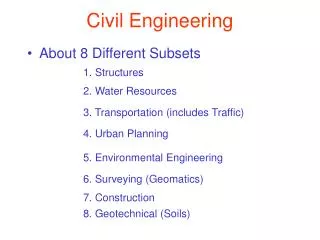
Agenda • Civil Engineering study progress since Berlin 2017 • Update on the principal structures • Tunnel cross-section and Junction cavern layout options • Alignment and Geology • Interaction region design • Construction cost and schedule • Ground Investigation Planning and Future Steps
Study progress 2017/18 Phase 3 of cost and schedule study launched. • Produce a cost and schedule estimate that is compatible with the CDR baseline. Ongoing work: • Surface site investigation • Spoil management study • Site investigation planning • Cost and schedule updates Design development with integration, including study to investigate feasibility of connections to FCC. • Cost and schedule round up for all 3 machines: FCC-hh, FCC-ee and FCC-eh • CDR writing • Alignment update following geological review of key areas: • Lake crossing • Arve and Rhone Valleys • Led to the lowering of the alignment by 30 m. Including the FCC-eh Machine February 2018 September 2017 March 2018 August 2017 Ongoing
Schematic Layout of FCC-eh FCC experimental point. BDS Linac. • Tunnel Dimensions: • 400m Beam Delivery System (BDS) • 1070m Linac • 979m radius arcs (x2) • 400m drift section. • Total Length of main tunnel = 9091m. • Total Length of RF Tunnel = 2140m
Structure schedule for FCC-eh RF Galleries
Scope of FCC-eh Structures • Small Experimental Caverns • 30 m x 35 m x 66m Shafts: 2 x Service shafts: 9 m dia. x 175 m depth • Junction Caverns • 16.8 m x 15 m x 100 m • 25 m x 15 m x 50 m • 16.8 m x 15 m x 90 m • Service Caverns • 25 m x 15 m x 50 m • Tunnels: • 9.091 km of 5.5m dia. machine tunnel. • 2 x 1.04 km of 5.5m dia RF tunnel.
Typical tunnel cross-section Steel structure with passive fire protection. Connection: Pre-cast concrete segmental lining Cast-in-situ concrete invert Pre-cast concrete element
Junction cavern refinement • Junction caverns are required for structural stability when tunnels of similar size connect. • By evaluating each case individually, it was possible to omit some junction caverns • The remaining caverns have been grouped into 3 types. (Type 1 below indicates no cavern is needed) • Types 2, 3 and 4 are utilised for the FCC-eh machine.
Alignment and Geology • After another round of alignment and geological optimisation the FCC-eh machine remains at FCC experimental point L provides the following benefits: • Lowest risk for construction, lowest geological risk. • Fastest and cheapest construction • Close to existing CERN land.
Geological Uncertainty along Alignment • Seismic and borehole information for lake crossing from proposed road tunnel, but layered nature of lake bed leads to uncertainty. • FCC-eh Located at Point L • Information near to CERN is strong due to previous experience on LEP/LHC. • Multiple deep boreholes in the area. B A C • Location of the interface between molasse and molasse subalpine not certain, tunnel alignment in proximity. L D K • Moraine/molasse interface not certain, cavern close to interface. • Lack of deep boreholes in area. • Alignment close to limestone rockhead E J • No deep borehole information available in the area. • Complex faulted region. • Molasse/limestone interface not certain. F • Limestone formation known, but characteristics and locations of karsts unknown. G I H
Experimental point layout options • With 45 m spacing in good molasse, the rock pillar alone is sufficient. • Cheapest and lowest risk option for CE • Separation to be maintained for the FCC & FCC-eh tunnels and caverns where possible. • With a 10 m spacing it is feasible but a high strength concrete pillar is required.
Cost and schedule study progress • Phase 1 • Cost & Schedule estimate for “baseline” single tunnel design. • Phase 2 • Cost & Schedule implications of variations considered: • Double tunnel design • Shallow option • Alternative tunnel diameters • Alternative shaft diameters • Alternative cavern dimensions • ee machine requirements • Alternative schedule + Inclined access tunnels • Phase 3 • Refinement of results from Phases 1 and 2: • Review to include updates made to baselined design. • Incorporate desirable variations from Phase 2. • Incorporate FCC-eh Design
Construction Schedule • FCC-eh Schedule Considerations: • The eh Civil Engineering work is expected to be undertaken as part of the FCC construction • This schedule is therefore based on the schedule produced for the FCC main tunnel. • FCC overall CE schedule 6.5 years FCC-eh: 4.5 years
Cost Update Contributors to cost changes RF Galleries • Tunnel Length for FCC is 9091m • Ventilation ducts and fire compartments Included • Connection Tunnels between RF Gallery and Main Tunnel. • Increased Shaft depth to a total of 350m • Consultancy and contractors profit % increase • Injection Cavern added to structures schedule • Price escalation
Spoil Management • Production of up to 42,000m3 per month • 9million cubic meters to dispose • Can the molasse be re-used? Assumed bulking factor of 1.3 Total Spoil volume of FCC-eh = 598,140m3
Ground Investigation Planning • Types of site investigation: • Collection of existing information • Walkover survey • Geophysical investigation • Boreholes • Site testing (egInsitu stress test, point load testing, SPT) • Rock laboratory testing. Geothermal site investigation in Satigny 2017/2018 (500m deep)
Other Future Steps • A further round of alignment optimisation for FCC following input from surface site investigations and potentially ground investigations. • This will require an optimisation of the FCC-eh machine when/if the alignment is optimised. • Continuing to work with integration to refine designs for all structures and integrate the eh machine with the FCC machine. • Spoil disposal planning for FCC-eh as part of the overall spoil disposal plan. • A further cost update to be undertaken to refine the FCC-eh Costs.