Download
1 / 1
10 likes | 103 Views
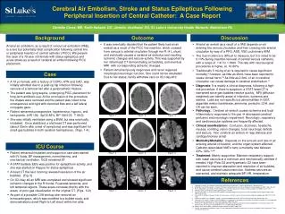
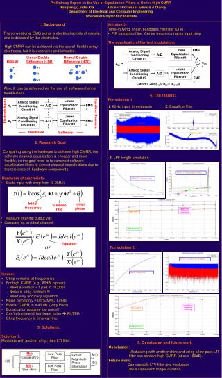
Linear Double Difference (LDD ). Normal Double Difference (NDD ). Bipolar. +1. +1. +1. +1. +1. -4. -1. -2. +1. +1. Electrode Inputs. Equalized Channels. Zoom view. Linear Equalization Filter #1. EMG 1. Analog Signal Conditioning Circuit #1. A/D. +. S. e OUT. e IN. -.

E N D
Linear Double Difference (LDD) Normal Double Difference (NDD) Bipolar +1 +1 +1 +1 +1 -4 -1 -2 +1 +1 Electrode Inputs Equalized Channels Zoom view Linear Equalization Filter #1 EMG1 Analog Signal Conditioning Circuit #1 A/D + S eOUT eIN - Linear Equalization Filter #2 Analog Signal Conditioning Circuit #2 A/D EMG2 Linear Equalization Filter #1 Linear Equalization Filter #2 CMRR = 20log10(2|eIN| / |eOUT|) Analog Signal Conditioning Circuit #2 Analog Signal Conditioning Circuit #1 A/D A/D e1 e2 EMG2 EMG1 INPUT = Chirp only (0-1kHz) INPUT = Noise only Initial frequency Initial phase ½ sweep rate Equalization; Frequency Smoothing Equalization Hardware Software No Equalization Equalizer INPUT = Chirp only (0-1kHz) INPUT = Noise only Equalization; Frequency Smoothing Equalization Mix: Sine chirp Mix: Cosine chirp Low Pass Filter Low Pass Filter No Equalization • Background • The conventional EMG signal is electrical activity of muscle, and is detected by the electrodes. • High CMRR can be achieved via the use of flexible array electrodes, but it is expensive and inflexible. • Solution 2: • Time–varying, linear, bandpass FIR filter (LTV). • FIR bandpass filter: Center frequency tracks input chirp • The equalization filter test modulation: Preliminary Report on the Use of Equalization Filters to Derive High CMRRHongfang (Linda) Xia Advisor: Professor Edward A ClancyDepartment of Electrical and Computer Engineering Worcester Polytechnic Institute Also, it can be achieved via the use of software channel equalization. 4. The results: For solution 1: 2. Equalizer filter 1. 60Hz input, time domain • 2. Research Goal • Comparing using the hardware to achieve high CMRR, the software channel equalization is cheaper and more flexible, so the goal here is to construct software equalization filters to correct channel imperfections due to the tolerance of hardware components. • Hardware characteristic • Excite input with chirp form (0-2kHz): 3. LPF length simulation • Measure channel output y(t): • Compare vs. an ideal channel: For solution 2: • Issues: • Chirp contains all frequencies. • For high CMRR (e.g., 80dB, bipolar): • - Need accuracy > 1 part in 10,000! • - Noise is a big problem!!!! • - Need very accuracy algorithm. • Noise commonly ≈ 0.5% MVC Limits. • Bipolar CMRR to ≈ 45 dB (Very Poor). • Equalization requires low noise!! • Can’t eliminate all hardware noise FILTER • Chirp frequency is time-varying. • 3. Solutions: • Solution 1: • Modulate with another chirp, then LTI filter. 5. Conclusion and future work Conclusion: Modulating with another chirp and using a low pass LTI filter can achieve high CMRR (above ~80dB). Future work: Can cascade LTV filter and modulator. Use a signal with longer duration. … M(t) Extract Magnitude, Phase Information x(t) Φ(t)