Download

1 / 32
320 likes | 560 Views
Engine Speed Control for HMMWV. Members. Faculty Advisor Industrial Advisor Dr. Marshall Molen Mr. Dan Harkins Picture Unavailable Team Members Team Leader

E N D
Members • Faculty AdvisorIndustrial Advisor Dr. Marshall MolenMr.Dan HarkinsPicture Unavailable • Team Members Team Leader Daniel Kennedy Patrick McNally Catalina Olarte Jarrod Fortinberry Overcurrent Protection Stepper Motor Research Website Design Research Signal Processing Power Electronics Simulations Microcontroller Interface
Overview • United States Army wants to deploy high-power intelligence gathering equipment in remote areas • Integrating these systems into Humvees would allow remote deployment • Power the systems with the Humvee’s electrical system
Problem • Humvee alternator is unable to supply enough power at idle engine speeds Effects • Load does not receive required power • Increased wear and tear on the engine and alternator
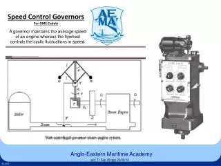
Solution • Adjust engine RPMs according to electrical load • How? Design an electronic engine governor • Governor - A feedback device on an engine that is used to provide automatic control of RPMs
Design Constraints • Operating Temperature Range : -20˚C to +70˚C • Controller Accuracy: +/- 3.0% • Tachometer Accuracy: +/- .5% • Cost Of Supplies: < $600 • Reliability: 10 years based on HMMWV’s lifetime • Installation time of 2-4 hours by mechanic • Enclosure Rating: NEMA 6 or IP67 (Temporary Submersion) • Controller can only be activated while vehicle is stationary
Initial Questions • How to measure RPMs of the engine? • How to measure electrical load?
RPM Signal • Magnetic Sensor on Flywheel • Time-Consuming Installation • 138 Pulse Per Revolution • 2V-4V pk-pk sin wave • Alternator • Easy Access for Installation • Only 16 Pulses Per Revolution • 28 V pk-pk square wave
Field Current Field Current Field Current a) b) c) Alternator Alternator Alternator Battery Electrical Load Battery Electrical Load Battery Electrical Load Electrical Load • Load Current << Max Alternator Current • Load Current < Max Alternator Current • Load Current > Max Alternator Current
Load Measurement Options • Load Current • Direct measurement of load • Large amounts of current • Battery Current • Smaller Current • Easy to determine if load is too large for alternator • Field Current • Probably the best measurement of load • Not characterized
System Overview Actuator PIC User Interface Battery Current RPM Reading Engine / Alternator Battery Load
System Specifics Tach Signal Battery Current DC Current Probe F/V Converter Microcontroller H-bridge Stepper Motor
System Overview Actuator PIC User Interface Battery Current RPM Reading Engine / Alternator Battery Load
Actuator • Links Mechanical Part of Project with the Electronic Part • Hybrid, Bipolar Stepper Motor • 12 V, 0.4 A, 2-phase motor • Driver circuit must be used to supply ample current • Driver circuit must be able to drive positive and negative current through the motor (H-bridge circuit) • Electromagnet • 12 VDC • Attached to stepper motor; moves the throttle cable
System Overview Actuator PIC User Interface Battery Current RPM Reading Engine / Alternator Battery Load
System Overview Actuator PIC User Interface Battery Current RPM Reading Engine / Alternator Battery Load
Problem • RPM reading from the alternator must be converted into RPMs for engine. But what if the engine to alternator pulley ratio is different?
Solution • Add potentiometer to the F/V circuit to allow Army mechanics to calibrate the system.
Problem • Stepper motor does not have enough torque to operate the throttle.
Solution • Instead of simple H-bridge, use a chopper circuit.
Acknowledgement • Dr. Marshall Molen • Evan Burnett