Download
1 / 33
511 likes | 1.61k Views
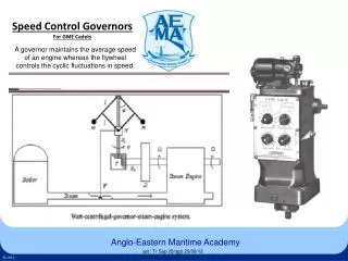
A governor maintains the average speed of an engine whereas the flywheel controls the cyclic fluctuations in speed. Speed Control Governors For GME Cadets. ajit / Tr Sup ( Engg ) 29/06/12. Contents.

E N D
A governor maintains the average speed of an engine whereas the flywheel controls the cyclic fluctuations in speed. Speed Control GovernorsFor GME Cadets ajit / Tr Sup (Engg) 29/06/12
Contents Governor classification U Tube Video on Diesel Engine GovernorsA. Classification of Speed Governors as per the control media used B. Classification of Speed Governors as per the functions they carry out C. Classification of Speed Governors as per the speed setting arrangement Further classification of Speed Governors based upon their operating principles Dead Weight type basic centrifugal governor Mechanical / Hydraulic, Relay or Indirect acting type Governor Speed droop (Permanent) , Feed back Speed droop (Transient) , Compensation Woodward governor nomenclature SG, UG8, UG40, PG200, PGA200 etc. Controls on Woodward UG8 Speed droop Knob, Synchronizer Knob, Load limit Knob, Synchronizer indicator Knob Woodward UG 8 Internals UG 8 Governor Operation Load Reduction 1 Load Reduction 2 Load Reduction 3 Load Increase 1 Load Increase 2 Load Increase 3 Initial set up & Adjustments of Governor Speed droop & Steady state speed regulation Isochronous Governor Droop and its relation to load division Methods of speed setting The A/E governor The M/E governor Equilibrium position of governor flyweights and balancing of forces Speeder Spring rate and its effect on governor stability Over speed governor & Speed regulating governor spring rate selection conical or trumphet shaped spring as the SPEEDER SPRING Some important features & terms in governors ajit / Tr Sup (Engg) 29/06/12
Index A. Classification of Speed Governors as per the control media used. 1. Mechanical or Direct acting type When the movement of the flyweights directly operate the engine fuel control rack, it is called a direct acting governor. They need huge fly weights so that enough power can be obtained for moving the racks. 2. Mechanical / Hydraulic, Relay or Indirect acting type This type has the movement of the flyweights operating a pilot valve plunger only. The operation of the rack being through a power piston operated by hydraulic pressure controlled by the pilot valve. 3. Electronic governor The speed governor can considered to be of three main parts, 1. Speed sensing 2. Control function 3. Actuator. An electronic governor may have its speed sensing and the control functions electronically carried out. The actuating of the rack may be done by an electric motor or by a pneumatic actuator. ajit / Tr Sup (Engg) 29/06/12
Index B. Classification of Speed Governors as per the functions they carry out. 1. Regulating governors They are constantly positioning the fuel rack at all speeds. Two kinds of regulating governors are possible, Constant speed Where the set speed of the governor cannot be altered. Variable speed Where the set speed can be varied to control load. 2. Speed limiting governors Which act only to keep speed within the normal range, not allowing over speeding or under speeding. They are not acting when speed is in normal range. These type of governors are found in vehicle engines. 3. Overspeed governors (overspeed trip / shutdown) They act only in case of an overspeed. An overspeed governor shuts down or trips the engine as compared to the others which regulate the fuel rack. ajit / Tr Sup (Engg) 29/06/12
Index C. Classification of Speed Governors as per the speed setting arrangement 1. Lever type Lever type governor is one in which the speed setting is carried out by a lever which adjusts the speeder spring tension. 2. Dial type Dial type governor is one in which the speed setting is done by turning a dial on the governor. ajit / Tr Sup (Engg) 29/06/12
Index Further classification of Speed Governors based upon their operating principles. • Basic classification of mechanical speed governors based on operating principle are • Inertia governors • Centrifugal governors • a. Gravity Controlled / Dead Weight type • 1. Watt • 2. Porter • 2. Proell • b. Hartnell (Spring controlled) • In the former type the centrifugal force is relied on for operation. The flyballs or flyweights responds to change in rpm. • In the latter type the inertia force is relied on for operation. The inertia of rotating weights causes a shifting of weights when acceleration or deceleration occurs. This rate of change in rpm is detected by inertia • governors and hence they are more sensitive that centrifugal governors. It should be noted that it only detects rate of change of speed and hence cannot be used independently for speed control. • A centrifugal governor can be dead weight type also called gravity controlled, in which the gravity force is what acts against the centrifugal force. Watt governors fall in this category, Porter and Proell are of same type with some modifications. These governors are inherently stable. • The centrifugal governor that is used today is of Hartnell type where the gravity force is replaced by spring force. The spring rate can be varied as necessary and the spring rate decides the stability of the governor. Linear or non linear springs (trumpet / conical) can be used. ajit / Tr Sup (Engg) 29/06/12
Index Dead Weight type basic centrifugal governor Draw Backs Torque output low, depends on flyweight size Large flyweights required to reduce static friction effects Large flyweights leads to inertia effects low rpm, less sensitive Speed droop inherent ajit / Tr Sup (Engg) 29/06/12
Index Mechanical / Hydraulic, Relay or Indirect acting type Governor Advantages Output no longer linked to fly weight size Smaller flyweight size lead to no inertia effects higher rpm, more sensitive Drawbacks Over sensitive Will hunt ajit / Tr Sup (Engg) 29/06/12
Index Speed droop (Permanent) , Feed back A mechanical negative feed back arrangement is provided Feed back is having the movement of the power piston transmitted to the speeder spring Negative feed back is so as to reduce its tension as the fuel in increased Negative Feed back introduces stability But introduces a permanent speed droop. ajit / Tr Sup (Engg) 29/06/12
Index Speed droop (Transient) , Compensation A hydraulic negative feed back arrangement is provided by the compensation system The compensation system consists of the Compensating spring, actuating piston and receiving piston. A compensating needle valve setting decides the rate of oil flow in or out of the compensation system Provides a transient speed droop As the fuel is being increased, the speed setting is reduced temporarily. which is set back to normal slowly as the engine rpm recovers. Compensation gives stability without introducing droop, it enables isochronous operation. ajit / Tr Sup (Engg) 29/06/12
Index Woodward governor nomenclature SG, UG8, UG40, PG200, PGA200 etc. SG - Simple Governor Simple Proportional governor, without compensation. Has adjustable droop, cannot operate isochronously. Pressure oil has to be supplied from the engine, no attached pump or sump. UG - Universal Governor Governors with Adjustable compensation & Adjustable droop. Can operate isochronously or with droop. Has attached pump and sump. PG - Pressure compensating hydraulic Governor No adjustment of droop or compensation. Has limited compensation. PGA - PG + Air speed setting PGA/EG - PGA + Electric Actuator PGA/TL - PGA + Torque Limiter The number "8/40/200" indicates the maximum torque that the terminal shaft can apply, called the "stalling work capacity". It is the torque specified in "foot pounds". Woodward UG8 Specs Rated for drive from 375 to 1500 rpm on drive shaft. Ratio of 1 : 2.2. ajit / Tr Sup (Engg) 29/06/12
Index Controls on Woodward UG8 Controls on Woodward UG8 Speed droop Knob Synchronizer Knob Load limit Knob Synchronizer indicator Knob Speed setting motor and friction drive Shut down solenoid ajit / Tr Sup (Engg) 29/06/12
Index Speed droop Knob, Synchronizer Knob, Load limit Knob, Synchronizer indicator Knob Speed droop Knob The graduations are from 0 to 100, this does not indicate percentage droop. For stand alone engines, speed droop can be set to zero. For engines interconnected electrically (AC busbar) or mechanically, the speed droop is to be set at the lowest setting which gives stable load division. Normally 30 to 50 on the dial. If speed droop is set to zero, the governor operates isochronously. Synchronizer Knob This knob is free to turn for many rotations. This changes the speeder spring tension, thus changing the set speed of the governor. Load limit Knob This scale is graduated from 0 to 10. A pointer below the knob indicates the power piston position over this scale. The knob can be put to any postion and the rack movement is limited to that position. This limits hydraulically the maximum possible movement of the terminal shaft. The load limit can be used to, limit fuel during a start, Shut down a running engine, Limit the maximum load on the engine. Synchronizer indicator Knob This knob is coupled by gears to synchronizer knob. The gear ratio is in such a way that the indicator turns one division for every one revolution of the synchronozer knob. This indicates the position of the synchronizer knob over its range of movement. ajit / Tr Sup (Engg) 29/06/12
Index Woodward UG 8 Internals ajit / Tr Sup (Engg) 29/06/12
Index Load is decreased and speed increases As speed increases, FLY BALLS move out raising SPEEDER ROD and inner end of FLOATING LEVER, thus raising PILOT PLUNGER and uncovering REGULATING PORT in PILOT VALVE BUSHING Uncovering of REGULATING PORT opens bottom of POWER CYLINDER to sump and will allow oil pressure in top of POWER CYLINDER to move POWER PISTON down Load Reduction 1 ajit / Tr Sup (Engg) 29/06/12
Index Oil pressure moves POWER PISTON down rotating TERMINAL SHAFT in the direction to decrease fuel As the POWER PISTON moves down, ACTUATING COMPENSATING PISTON moves up and draws RECEIVING COMPENSATING PISTON down compressing COMPENSATING SPRING and lowering outer end of FLOATING LEVER and PILOT VALVE PLUNGER Movement of POWER PISTON, ACTUATING COMPENSATING PISTON, RECEIVING COMPENSATING PISTON and PILOT VALVE PLUNGER continues until REGULATING PORT in BUSHING is covered by land on PLUNGER As soon as REGULATING PORT is covered, POWER PISTON and TERMINAL SHAFT are stopped at a position corresponding to decreased fuel needed to run engine at normal speed under decreased load. Load Reduction 2 ajit / Tr Sup (Engg) 29/06/12
Index Load Reduction 3 As speed decreases to normal, FLYBALLS return to normal position lowering the SPEEDER ROD to normal position. RECEIVING COMPENSATING PISTON is returned to normal position by COMPENSATING SPRING at the same rate as SPEEDER ROD thus keeping REGULATING PORT in PILOT VALVE BUSHING covered by land on PILOT VALVE PLUNGER. Flow of oil through COMPENSATING NEEDLE VALVE determines rate at which RECEIVING COMPENSATING PISTON is returned to normal. At completion of cycle, FLYBALLS, SPEEDER ROD, PILOT VALVE PLUNGER, and RECEIVING COMPENSATING PISTON are in normal position. POWER PISTON and TERMINAL SHAFT are stationary at a position corresponding to decreased fuel necessary to run engine at normal speed under decreased load. ajit / Tr Sup (Engg) 29/06/12
Index Load Increase 1 Load is increased and speed decreases. As speed decreases, FLYBALLS move in lowering the SPEEDER ROD and inner end of FLOATING LEVER, thus lowering the PILOT VALVE PLUNGER and uncovering the regulating port of the PILOT VALVE BUSHING. Uncovering of REGULATING PORT admits pressure oil to the bottom of the POWER CYLINDER. Since bottom area of POWER PISTON is greater that the top area, oil pressure will move PISTON up ajit / Tr Sup (Engg) 29/06/12
Index Load Increase 2 Oil pressure moves POWER PISTON up and rotates the TERMINAL SHAFT in direction to increase fuel. As POWER PISTON moves up, ACTUATING COMPENSATING PISTON moves down and forces the RECEIVING COMPENSATING PISTON up compressing COMPENSATING SPRING and raising outer end of FLOATING LEVER and PILOT VALVE PLUNGER Movement of POWER PISTON, ACTUATING COMPENSATING PISTON, RECEIVING COMPENSATING PISTON and PILOT VALVE PLUNGER continues until REGULATING PORT in PILOT VALVE BUSHING is covered by land on PLUNGER As soon as REGULATING PORT is covered, POWER PISTON and TERMINAL SHAFT are stopped at a point corresponding to increased fuel needed to run engine at normal speed under increased load ajit / Tr Sup (Engg) 29/06/12
Index Load Increase 3 As speed increases to normal, FLYBALLS return to normal position raising SPEEDER ROD to normal position. RECEIVING COMPENSATING PISTON is returned to normal position by COMPENSATING SPRING at the same rate as SPEEDER ROD, thus keeping REGULATING SHAFT in PILOT VALVE BUSHING covered by land on PILOT VALVE PLUNGER. Flow of oil through COMPENSATING NEEDLE VALVE determines rate at which RECEIVING COMPENSATING PISTON is returned to normal At completion of cycle, FLYBALLS, SPEEDER ROD, PILOT VALVE PLUNGER and RECEIVING COMPENSATING PISTON are in normal positions, POWER PISTON and TERMINAL SHAFT are stationary at a position corresponding to increase fuel necessary to run engine at normal speed under increased load. ajit / Tr Sup (Engg) 29/06/12
Index Initial set up & Adjustments of Governor Initial adjustments after setting up, or after overhauling, oil change (air bleeding). Procedure of adjustments to the compensating system. Compensation lever adjustment Compensation needle adjustment Hunting, high overspeeds and underspeeds and slow return to normal speed following load changes are results of incorrect compensation adjustment. Adjustment should be done when the engine has been operating for some time and the governor and its oil has attained operating temperatures. The engine is to be off load, at the normal operating rpm. The compensating lever is put to maximum upward position and the needle valve opened four to five turns outward. This will cause the engine to hunt which will bleed trapped air form passages. Then the lever is put to minimum and the needle valve closed gradually till hunting stops. If hunting doesn't stop at all till full closing of the needle valve, the compensating lever can be raised by two graduations and then procedure repeated. The needle valve should be ideally open from closed position only by about 3/4 th turn, maximum. If the needle valve is closed more than needed, slow return to normal speed will result following a load change. If the compensation lever is moved more towards maximum than needed, excessive speed change upon load change will result. ajit / Tr Sup (Engg) 29/06/12
Index Speed droop & Steady state speed regulation Speed droop is the drop in rpm that occurs as with full travel of the power piston, expressed as a percentage of full load rpm. Steady state speed regulation is percentage change in speed from no load to full load expressed as a percentage of the full load rpm. If N1 (720, 60 Hz for 10 poles) is the no load rpm and N2 (690, 57.5 Hz for 10 poles) the full load rpm, then speed droop is (N1 - N2)/ N2 * 100. (4.3%). The term steady state speed regulation is mostly used to mean the same as speed droop. It does mean the same as speed droop, when the fuel rack and governor linkage is such that, full travel of governor power piston occurs as the engine goes from no load to full load. Supposing only 50 % of the governor terminal shaft movement is utilized for the engine to change from no load to full load and the governor is set to speed droop of 4 %, then in this case the steady state speed regulation is only 2 %. It is generally reccommededthat only about 2/3 rds of the power piston travel is utilized for full load / speed range of the engine. In such a case speed droop and steady state regulation would be different. ajit / Tr Sup (Engg) 29/06/12
Index Isochronous Governor A governor which maintains a steady speed at the set value irrespective of load changes is called an isochronous governor. A constant speed or variable speed governor can be isochronous. Isochronous operation deals with the ability of the governor to maintain the set speed whereas constant & variable speed deals with the provision in the governor to change the set speed. Isochronous operation is obtained if speed droop is set to zero. ajit / Tr Sup (Engg) 29/06/12
Index Droop and its relation to load division Stable load division between two engines feeding power into a common system Supposing the system is running initially with load L1 on both machines and at an rpm of r1. When additional load in imposed, the system rpm has to drop since droop is there in both machines. If the system rpm drops to r2, the corresponding load changes will have to follow the curves. It can be seen that Engine 1 having lower droop will take up more load than the other. ajit / Tr Sup (Engg) 29/06/12
Index Methods of speed setting (Adjustment of SPEEDER SPRING tension) Manual turn of knob which adjusts speeder spring directly.(A/E governor). Turning the speed set mechanism by an electric reversible motor from remote. (A/E governor). Remote speed set pneumatic signal, through a pneumatic positioner controlling the speed set lever. (lever type governor) Remote speed set pneumatic signal acting on the speeder spring directly through the pneumatic / hydraulic positioner built into the governor. ajit / Tr Sup (Engg) 29/06/12
Index The A/E governor It is a constant speed governor, within a narrow range, speed variation is possible for synchronizing of alternators. Speed droop setting is needed since generators have to run in parallel. If stable division of load is to be achieved, isochronous operation is not possible. The remote speed setting is by an electric motor driving the speeder spring setting mechanism. The power output of the governor is less since the engine is small. The generator governor should be able to maintain engine speed during load changes as laid out by rules. (see below) Requirements of A/E governor With a load change of 25 % of the full rated load, the speed change is not greater than 2.5 %. Within two secs the speed should remain within one % of the final steady state speed and within four secs, the speed should be within half % of the final steady state speed. ajit / Tr Sup (Engg) 29/06/12
Index The M/E governor The main engine governor is a variable speed governor which allows speed to be controlled form lowest to the maximum limit. Speed droop setting is not needed other than for twin engined vessels which feed into a common shaft for driving the propeller. Twin engined vessels where there is no mechanical coupling between engine do not have to have speed droop setting. The remote speed setting is pneumatic, either through a positioner with a lever type governor or by pneumatic / hydraulic built in arrangement. Being used on large engines, the power output is higher and an amplifier is used in case the power output is not sufficient to move the rack. Scavenge air pressure fuel limiter This system senses the scavenge air pressure from the scavenge air box and releases fuel as a function of the scavenge air pressure. This ensures no more fuel than that which can burn fully is released, which ensures proper combustion during load increase. Speed setting fuel limiter or Torque limiter This is a system which releases fuel as a function of the speed set air signal to governor. This prevents engine overloading and also lower fuel admission at start. The reversible attached oil pump The attached oil pump of the governor has to be having an arrangement to deliver oil irrespective of the running direction, for reversible main engines. ajit / Tr Sup (Engg) 29/06/12
Index Balance of forces in a governor Two opposing forces are at balance in equilibrium position 1. The centrifugal force of flyweights 2. The Gravity OR Spring force The centrifugal force, FC = m ω2 r (mv 2 /r as v = r ω) The spring force , FS = spring constant × deflection Deflection is proportional to radius r Therefore, both FC & FS are functions of the radius ‘r’ of flyweights for a given rpm Both forces FC & FS (centrifugal & gravity / spring) can be plotted against radius ‘r’ For a given rpm, the centrifugal force is a straight line passing through the origin Considering a linear rate spring, the spring force line too would be straight. The point of intersection of the two lines will be the radius of flyweights at equilibrium. ajit / Tr Sup (Engg) 29/06/12
Index Speeder Spring rate & governor stability For a governor to be stable, the rate of spring force should be higher that that of the centrifugal force at the point of intersection of the two lines. In the left graph, the spring rate is higher at the point of intersection in case of drop in rpm, the centrifugal force and spring force both drop and find a new equilibrium position at a reduced radius in case of rise in rpm, the centrifugal force and spring force both rise and find a new equilibrium position at an increased radius In the right graph, the spring rate is lower at the point of intersection in case of drop in rpm, the centrifugal force reduces, radius also reduces, the increaseing spring force (over centrifugal force) takes the flyweights to the inner extreme position In case of rise in rpm, the centrifugal force increases, radius also increases, the rising centrifugal force (over spring force takes the flyweights to outer extreme position ajit / Tr Sup (Engg) 29/06/12
Index Regulating governor & Over speed governor, spring rate selection Regulating governor spring rate is as per graph shown on left. For every rpm there is a different equilibrium position. Over speed trip governor’s spring rate is chosen to be in the unstable range. There is only one equilibrium rpm and the flyweights takes extreme positions when rpm changes. When the equilibrium rpm is reached, the flyweights start moving out, increasing the radius and corresponding increase in centrifugal force over the spring force. Since the spring rate is lower, this moving out of flyweights is very positive and with increasing force. ajit / Tr Sup (Engg) 29/06/12
Index Selection of conical or trumphet shaped spring as the SPEEDER SPRING in a governor Graph on right shows how a non linear speeder spring (conical OR trumphet shaped spring) makes the governor more stable at a wide range of rpms. Graph on right shows How a non linear conical speeder spring makes the governor more sensitive. Percentage change in load is plotted against spring deflection. It can be seen that the deflection for a small change in load is high in case of a non linear spring and the deflection at a high load change is not correspondingly higher. ajit / Tr Sup (Engg) 29/06/12
Index Some important features & terms in governors 1. Speed droop (Permanent) , Feed back 2. Speed droop (Transient) , Compensation 3. Steady state speed regulation. 4. Isochronous 5. Boost air to governor (Booster) 6. Pre set air to governor 7. False scavenge air pressure to governor (Cancellation of scavenge air pressure fuel limiter ) 8. Hydraulic Amplifier In a mechanical hydraulic governor, the dead band effects are reduced by, 1. A conical speeder spring 2. Having the flyweights rotate at a higher rpm than the engine, which increases sensitivity. 3. Reducing static friction effects by rotating the pilot valve bushing. ajit / Tr Sup (Engg) 29/06/12
Index U Tube Video on Diesel Engine Governors ajit / Tr Sup (Engg) 29/06/12