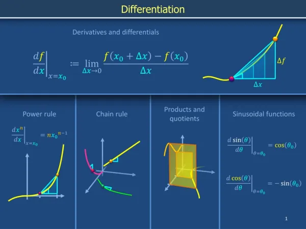
Sinusoidal Oscillators
Learn about sinusoidal oscillators, electronic circuits that produce periodic signals, and understand the impact of negative and positive feedback mechanisms on voltage gain and stability. Explore the importance of oscillators and their diverse applications in various electronic devices.

Sinusoidal Oscillators
E N D
Presentation Transcript
Definitions An electronic oscillator is an electronic circuit that produces a periodic, oscillating electronic signal, often a sine wave or a square wave. Oscillators convert direct current (DC) from a from a power supply to an alternating current (AC) signal. They are widely used in many electronic devices. An oscillator is a mechanical or electronic device that works on the principles of oscillation 1. Acircuit or instrument for producing an alternating current or voltageof a required frequency 2. Any instrument for producing oscillations Computers, clocks, watches, radios, and metal detectors are among the many devices that use oscillators.
Sinusoidal Oscillatorss • Two types of feedback is used • Negative Feedback • Complete or Part of the output of an amplifier is applied to an input which is outoff phase with input then such feedback is referred as negative feedback • It affects overall voltage gain( reduces) but stability & bandwidth increases and distortion reduces. Also improvement in Ri & Ro(some circuit) • Positive Feedback • Complete or Part of the output signal is feedback to the input which is in phase with input then such feedback is referred to as positive feedback • The use of +FB, which results in a closed loop gain greater than 1 • Due to +ve FB an oscillation can occur, ie. Providing a source of ac voltage at a desired frequency called an oscillator
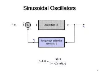
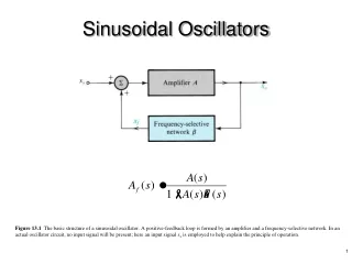
Sinusoidal Oscillators Amplifier(Av) Feedback Circuit(k)
Sinusoidal Oscillatorss • Effect of positive feedback- • Avf = the overall gain with feedback Av = Vo/Vi = Av/(1-k*Av) Where, k is the portion of the output voltage feedback to the input Now if kAv is negative, Avf decreases but if kAv is positive the gain increase and as the amount of +ve FB increases, the gain will increase until it becomes infinite, but the output cannot be infinite. An output will develop as the circuit has stopped amplifying
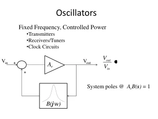
Sinusoidal Oscillatorss • Effect of positive feedback- • If the signal feedback is of proper magnitude and phase, the circuit produces oscillations ie. Alternating currents or voltages • To visualize the requirement of an oscillator, consider the circuit as shown in fig. oscillator is a circuit which deliver a sinusoidal output waveform without input signal excitation(ie. No input signal, Vi = 0) and FB is positive Vd = Vf+Vin Vo = AvVd, Vf = kVo Vo = Av(Vf+Vin) Vo/Vin = Avf Avf = Av/(1-kAv) Amplifier(Av) Amplifier(Av) ∑ Feedback Circuit(k) Feedback Circuit(k)
Sinusoidal Oscillatorss • Effect of positive feedback- • Avf = the overall gain with feedback = Vo/Vin = Av/(1-k*Av), However Vin = 0 but V0 ≠ 0 implies that 1-k*Av = 0 or k*Av =1 kAv = 1 0o or 1 360o, ----------(i) where kAv is the loop gain • It gives the two requirement for oscillations, ie the barkhausen criterion • 1. The magnitude of the loop gain must be at least unity( Av*K=1) • 2. The total phase shift around the loop (phase of the loop gain Av*K) must be equal to 0o or 360o
Sinusoidal Oscillators • The magnitude of the loop gain must be at least unity( Av*K=1), Avf Vo/Vin= Av/(1-kAv), • K*Av 1, then Avf ∞, which means that there exists an output voltage even in the absence of an externally applied signal voltage(Vin = 0) • If the transistor amplifier causes a phase shift of 180, the feedback circuit must provide an additional phase shift of 180, so that total phase around the loop is 360 or 0 • In every practical oscillator the loop gain is larger than unity and the amplitude of the oscillations is limited by the onset of the nonlinearity • Applications of Ocillators • An oscillator is required for many applications, as it can generate any frequency starting from audio frequency(20Hz-20KHz) upto video frequency(MHz-GHz) • Oscillator is used in radio transmission to produce HF carrier signal for modulation purposes • it can be used as signal generator for testing stereo, radio, TV receivers, etc • Very HF generators used for heating in industry/ other purposes
Sinusoidal Oscillatorss • Types of Oscillatorss • According to type of oscillations-Damped Oscillators Undamped Oscillators • According to type of Components used -RC Oscillators LC Oscillators Crystal Oscillators • According to frequency of oscillations-AF Oscillators RF Oscillators Video/Microwave Oscillators • According to type of waveform generated- Sinusoidal Oscillators Nonsinusoidal Oscillators
Sinusoidal Oscillatorss • Types of Sinusoidal Oscillatorss • According to type of Components used -RC Oscillators LC Oscillators Crystal Oscillators • RC Oscillators –Phase shift Oscillators Wain bridge Oscillators LC Oscillators Crystal Oscillators
Sinusoidal Oscillatorss • The Sinusoidal Oscillatorss are classified according to the output signal waveform varies over one cylce of operation for a full cycle of input signal • Types of Sinusoidal Oscillatorss • Class A Sinusoidal Oscillatorss • Class B Sinusoidal Oscillatorss • Class AB Sinusoidal Oscillatorss • Class C Sinusoidal Oscillatorss • Class D Sinusoidal Oscillatorss
Sinusoidal Oscillators Types Class A The amplifier conducts through the full 360ο of the input. The output signal varies over one cycle of operation for one complete cycle of input signal. The Q-point is set or biased near the middle of the load line. So that at least half output signal swing may vary up and down without going to saturation or cut-off level Its power efficiency is about 25% to 50% Class B The amplifier conducts through 180ο of the input. The output signal varying over only one half of the input signal. The Q-point is set or biased at the cut-off point. Its power efficiency is about 78.5%
Class AB This is a compromise between the class A and B amplifiers. The amplifier conducts or output signal swing occurs between somewhere between 180ο and 360ο. The Q-point is located at a dc level above the zero IB of class B and above one half the VCC level of Class A ie. In between the mid-point and cut-off. Its power efficiency is about 50% to 78.5% Class C The amplifier conducts less than 180 of the input. The Q-point is biased below zero IB i.e is located below the cutoff level. Its power efficiency is about 90% Class D This is an amplifier that is biased especially for digital signals. Its output is like a pulse signal, which is on for short interval and off for a larger interval using digital techniques Sinusoidal Oscillators Types
Sinusoidal Oscillators • Performance Quantities of Sinusoidal Oscillators • The performance quantities or • criteria for a power amplifier are: • Collector Efficiency • Distortion • Power Dissipation Capability
Sinusoidal Oscillators • Collector Efficiency • The main criterion for a Sinusoidal Oscillators is not the power gain but the maximum ac power output. • An amplifier converts dc power from supply into ac power output. • Hence, the effectiveness of a Sinusoidal Oscillators is measured in terms of its ability to convert dc power from supply to ac output power. This is called as collector efficiency. • The collector efficiency is defined as the ratio of output power to the zero signal power or dc power supplied by the battery. • collector efficiency Expression
Sinusoidal Oscillators Expression for collector efficiency Collector efficiency,
Sinusoidal Oscillators (ii) Distortion The change of output wave shape from the input wave shape of an amplifier is known as distortion. Since , the transistor is a non-linear device, the output is not exactly like the input signal applied to it. Which means distortion occurs.
Sinusoidal Oscillators (iii) Power Dissipation Capability The ability of a power transistor to dissipate heat is known as power dissipation capability. A power transistor handles large currents and hence, heats up during operation. Since, any temperature change influences the operation of transistor, therefore, the transistor must dissipate this heat to its surroundings. To achieve this, normally a heat sink is attached to a power transistor case. The increased surface area allows heat to escape easily and keeps the case temperature of the transistor within permissible limit.
Sinusoidal Oscillators (iii) Power Dissipation Capability Diagram represent the power dissipated in the load and transistor • No input signal condition • (PB = 300mW) (ii) Full input signal condition (PB = 300mW) DC power dissipated in load 150mW DC power dissipated in load 150mW Average AC power dissipated in Load 75mW DC power dissipated in the Transistor 150mW 75mW Average power dissipated in Transistor
Class A Sinusoidal Oscillators In class A Sinusoidal Oscillators, the operating point is so adjusted that the collector current flows during the whole cycle of the input signal. The Sinusoidal Oscillators circuit is shown in the figure given below shows that the load is connected to the collector through an output transformer. The main purpose of the transformer is to provide perfect impedance matching so that the maximum power is delivered to the load.
Class A Sinusoidal Oscillators In class A Sinusoidal Oscillators, the operating point is so adjusted that the collector current flows during the whole cycle of the input signal. The Sinusoidal Oscillators circuit is shown in the figure given below shows that the load is connected to the collector through an output transformer. The main purpose of the transformer is to provide perfect impedance matching so that the maximum power is delivered to the load.
Class A Sinusoidal Oscillators • (The characteristics of Class A Sinusoidal Oscillators ) • The output current flows during the entire cycle of the ac input signal • The operation of the amplifier is limited to smaller central region of the load • line, so that it can operate in the linear region of the load line(It can amplify • small signals) • As transistors operates over the linear region of the load line, The output • waveform is almost similar to the input waveform • The ac power output per active device(transistor) is smaller than that of • Class B or C • The maximum possible overall efficiency of a class A series fed resistive • load is 25%(Very Poor) and for transformer coupled load it may increases to • 50%
Class A Sinusoidal Oscillators • The advantages of Class A Sinusoidal Oscillators are as follows − • The current flows for complete input cycle • It can amplify small signals • The output is same as input • No distortion is present • The ac Po per active device is smaller than that of Class B or C • The disadvantages of Class A Sinusoidal Oscillators are as follows − • Low power output • Low collector efficiency(25% or 50%)
Class B Sinusoidal Oscillators For class B operation of the amplifier, the biasing circuit is so adjusted that the operating point Q lies at the collector cut off voltage i.e. has zero collector current indicated that no biasing circuit is needed in this case. During the positive half cycle of the signal, the input circuit is forward biased & allow the collector current to flow while during the negative half cycle the input circuit is reverse biased & hence no current flows. Hence, in this amplifier, the negative half cycle of the signal is cut off. The collector efficiency of this amplifier is about 50% to 78.5% and has high output power. It is mostly used for power amplification in a push-pull arrangement.
Class B Sinusoidal Oscillators In class B Sinusoidal Oscillators, the operating point is so adjusted that the collector current flows only during the positive half cycle of the input signal. The circuit waveform of this amplifier is shown in given figure below.
Class B Sinusoidal Oscillators • Advantages of Class B Push pull amplifier: • The Circuit efficiency of a class B push pull amplifier is • 78.5%, which is much higher than that of class A • because no power loss is drawn from the dc supply • under no signal condition • The use of push pull arrangement in a class B amplifier • eliminates even order harmonics in the ac output signal • Because of the absence even order harmonics, the • circuit gives more output, per device, for a given amount • of distortion
Class B Sinusoidal Oscillators • Characteristics of Class B amplifier: • The output current flows only for half of the input signal • The transistors dissipates no power with zero input • signal. However it increases with the increase in the • amplitude of input signal which is opposite to class A • The average current drawn by the circuit is smaller than • that of class A, the amount of power dissipated by the • transistor is less, thus the overall efficiency of the circuit • is higher than that of class A(78.5%) • Lesser Heat output, Stable and Reliable • It uses 2 complementary transistors, one each for the • positive and negative cycle, to start conducting, it • requires 0.7 V