Oscillators
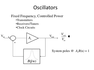
Oscillators. Communication Circuits Prof. M. Kamarei. Contents. Introduction General Considerations Ring Oscillators LC Oscillators Other Oscillators Voltage-Controlled Oscillators. Introduction. An oscillator is an autonomous circuit that converts DC power into a periodic waveform.


Oscillators
E N D
Presentation Transcript
Oscillators Communication Circuits Prof. M. Kamarei
Contents • Introduction • General Considerations • Ring Oscillators • LC Oscillators • Other Oscillators • Voltage-Controlled Oscillators Oscillators
Introduction • An oscillator is an autonomous circuit that converts DC power into a periodic waveform. • Oscillators are extensively used in both receive and transmit paths. They are used to provide the local oscillation for the mixers for up and down conversion. Oscillators
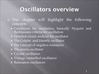
Contents • Introduction • General Considerations • Oscillator As Feedback System • Barkhausen Criteria • One-Port View of Resonator-Based Oscillators • Ring Oscillators • LC Oscillators • Other Oscillators • Voltage-Controlled Oscillators Oscillators
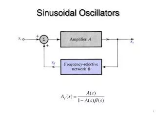
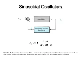
Oscillator As Feedback System • General feedback system • We assume s=jω • If there is a frequency in which H(jω0)=1180º then Oscillators
How a circuit can oscillate? • Input noise component at ω0 experiences unity gain and 180º phase shift in H(s). Then it is subtracted from input and gives larger difference. • The circuit continues regenerating and allows the ω0 to grow. Oscillators
How a circuit can oscillate? • Following the signal around the loop over several cycles: |H(jω0)|<1 |H(jω0)|>1 VX : Diverged Oscillators
Barkhausen Criteria • If a negative feedback circuit satisfies these two conditions, the circuit may oscillate at ω0 . • First criterion • We typically choose the loop gain to be at least two or three times more than the required value to ensure oscillation in presence temperature and process variations. Oscillators
Barkhausen Criteria • Second criterion • 180º phase shift criterion is equivalent to totally 360º loop phase shift. • (a): 180º phase shift is provided by negative feedback and another 180º by amplifier. • (b): 360º phase shift is totally provided by amplifier. • (c): 2nπ phase shift function same as (b) Oscillators
One-Port View of Resonator-Based Oscillators • Convenient for intuitive analysis • Here we seek to cancel out loss in tank with a negative resistance element • To achieve sustained oscillation, we must have: Oscillators
One-Port View of Resonator-Based Oscillators • Simple tank stimulated with current impulse • Decaying oscillation • In each cycle energy is lost in the resistor. • Canceling out RP with a negative resistance –RP • Stable oscillation Oscillators
Contents • Introduction • General Considerations • Ring Oscillators • Three-Stages Ring Oscillator • Natural Response • Some Other Implementations • LC Oscillators • Other Oscillators • Voltage-Controlled Oscillators Oscillators
Max. Phase shift of the output single pole Common-source negative gain Simple Ring Oscillator • Ring oscillator consists of some gain stages in a loop. • Dose a single common-source stage oscillate in loop? Max. Phase Shift = 180º + 90º < 360º No Oscillation Oscillators
Three-Stages Ring Oscillator • Negative feedback provides 180º phase shift. • 3 single pole gain stages can provide 0 to 270º phase shift • Phase criterion → Oscillation frequency Negative feedback Each stage phase delay Oscillators
Three-Stages Ring Oscillator • Gain criterion → The minimum gain of stages • Phase delay between 2 outputs: • 180º-60º=120º • The ability to generate multiple phases Oscillators
Three-Stages Ring Oscillator • Amplitude limiting Poles: Neglecting s1 Oscillators
Three-Stages Ring Oscillator (Root Locus) • A0=2 • Pure Complex poles → Stable oscillation • A0<2 • Circuit is stable (LHP poles) → Damped oscillation • A0>2 • Circuit is unstable (RHP poles) → Oscillation amplitude grows Oscillators
Natural Response • Given a transfer function • The total response of the system can be partitioned into the natural response and the forced response • where f2(si(t)) is the forced response whereas the first term f1() is the natural response of the system, even in the absence of the input signal. The natural response is determined by the initial conditions of the system. Oscillators
Real LHP Poles • Stable systems have all poles in the left-half plane (LHP). • Consider the natural response when the pole is on the negative real axis, such as s1 for our examples. • The response is a decaying exponential that dies away with a time-constant determined by the pole magnitude. Oscillators
Complex Conjugate LHP Poles • Since s2,3 are a complex conjugate pair • We can group these responses since a3 = a*2 into a single term • When the real part of the complex conjugate pair σ is negative, the response also decays exponentially. Oscillators
Complex Conjugate Poles (RHP) • When σ is positive (RHP), the response is an exponential growing oscillation at a frequency determined by the imaginary part ω0. • Thus we see for any amplifier with three identical poles, if feedback is applied with loop gain A03 > 23 = 8, the amplifier will oscillate. Oscillators
Frequency Domain Perspective • In the frequency domain perspective, we see that a feedback amplifier has a transfer function • If the loop gain a0 f = 8, then we have with purely imaginary poles at a frequency ωosc = √3×ω0 where the transfer function a(jωosc)f = -1 blows up. Apparently, the feedback amplifier has infinite gain at this frequency. Oscillators
Oscillation Build Up • In a real oscillator, as the oscillation amplitude increases, the stages in the signal path experience nonlinearity and eventually saturation, limiting the maximum amplitude. • We may say the poles being in the RHP and finally move to imaginary axis to stop the growth. • The circuit must spend enough time in saturation so that the average loop gain is still equal to unity. Oscillators
Some Other Implementations • Differential implementation Oscillators
Some Other Implementations • CMOS inverter ring oscillator Oscillators
Some Other Implementations • Five-stages single-ended ring oscillator • Four-stages differential ring oscillator Oscillators
Contents • Introduction • General Considerations • Ring Oscillators • LC Oscillators • RLC Circuits • A Simple Negative Resistance Oscillator • Differential Negative Resistance Oscilator • Colpitts Oscillator • Clapp Oscillator • Hartley Oscillator • CE and CC Oscillators • Pierce Oscillator • Other Oscillators • Voltage-Controlled Oscillators Oscillators
Ideal Tank RLC Circuits • Resonance of LC tank • The impedance of the circuit goes to infinity at resonance frequency • Q of the tank in infinite. (Q is the quality factor of the tank and defined as energy stored, divided by energy dissipated per cycle) Oscillators
Realistic Tank RLC Circuits • Realistic inductors suffer from resistive components. • Impedance peaks at resonance frequency. • Q in finite. Oscillators
L1ω/Rs=Q typically more than 3 Series RL to Parallel RL • In narrow frequency range it is possible to convert circuit to parallel configuration. • For the two impedances to be equivalent: Oscillators
A Simple RLC Model • RP is typically higher than RS • CP is equal to CS • In resonance • frequency the tank reduces to a simple resistor • Phase difference between voltage and current is zero • For ω<ω1 • Inductive behavior, Positive phase • Forω>ω1 • Capacitive behavior, Negative phase Oscillators
Small signal model If gm1=gm2=gm A Simple Negative Resistance OSC • How can a circuit provide negative resistance? • Positive feedback circuits with sufficient gain can provide it Oscillators
Differential A Simple Negative Resistance Osc. • Adding a tank to the negative resistor, we make an oscillator • For oscillation build-up • RP-2/gm 0 • Redrawing the oscillator • Converting to differential negative resistance oscillator Oscillators
Differential Negative Resistance Osc. • This type of oscillator structure is quite popular in current CMOS implementations • Advantages • Simple topology • Differential implementation (good for feeding differential circuits) • Good phase noise performance can be achieved Oscillators
Analysis of Negative Resistance Osc. (Step 1) • Derive a parallel RLC network that includes the loss of the tank inductor and capacitor • Typically, such loss is dominated by series resistance in the inductor Oscillators
Analysis of Negative Resistance Osc. (Step 2) • Split oscillator circuit into half circuits to simplify analysis • Leverages the fact that we can approximate Vs as being incremental ground (this is not quite true, but close enough) • Recognize that we have a diode connected device with a negative transconductance value • Replace with negative resistor • Note: Gm is large signal transconductance value Oscillators
Analysis of Negative Resistance Osc. (Step 3) • Design tank components to achieve high Q • Resulting Rp value is as large as possible • Choose bias current (Ibias) for large swing (without going far into Gm saturation) • We’ll estimate swing as a function of Ibias shortly • Choose transistor size to achieve adequately large gm1 • Usually twice as large as 1/Rp1 to guarantee startup Oscillators
Calculation of Oscillator Swing: Max. Sinusoidal Oscillation • If we assume the amplitude is large, Ibias is fully steered to one side at the peak and the bottom of the sinusoid: Oscillators
Calculation of Oscillator Swing: Square wave Oscillation • If amplitude is very large, we can assume I1(t) is a square wave • We are interested in determining fundamental component • (DC and harmonics filtered by tank) • Fundamental component is • Resulting oscillator amplitude Oscillators
Variations on a Theme • Biasing can come from top or bottom • Can use either NMOS, PMOS, or both for transconductor • Use of both NMOS and PMOS for coupled pair would appear to achieve better phase noise at a given power dissipation Oscillators
Colpitts Oscillator • Carryover from discrete designs in which single-ended approaches were preferred for simplicity • Achieves negative resistance with only one transistor • Differential structure can also be implemented, though • Good phase noise can be achieved, but not apparent there is an advantage of this design over negative resistance design for CMOS applications Oscillators
Analysis of Cap Transformer used in Colpitts • Voltage drop across RL is reduced by capacitive voltage divider • Assume that impedances of caps are less than RL at resonant frequency of tank (simplifies analysis) • Ratio of V1 to Vout set by caps and not RL • Power conservation leads to transformer relationship Oscillators
Simplified Model of Colpitts • Purpose of cap transformer • Reduces loading on tank • Reduces swing at source node (important for bipolar version) • Transformer ratio set to achieve best noise performance Oscillators
Design of Colpitts Oscillator • Design tank for high Q • Choose bias current (Ibias) for large swing (without going far into Gm saturation) • Choose transformer ratio for best noise • Rule of thumb: choose N = 1/5 according to Tom Lee • Choose transistor size to achieve adequately large gm1 Oscillators
Calculation of Oscillator Swing as a Function of Ibias • I1(t) consists of pulses whose shape and width are a function of the transistor behavior and transformer ratio • Approximate as narrow square wave pulses with width W • Fundamental component is • Resulting oscillator amplitude Oscillators
Clapp Oscillator • Same as Colpitts except that inductor portion of tank is isolated from the drain of the device • Allows inductor voltage to achieve a larger amplitude without exceeded the max allowable voltage at the drain • Good for achieving lower phase noise Oscillators
Simplified Model of Clapp Oscillator • Looks similar to Colpitts model • Be careful of parasitic resonances! Oscillators
Hartley Oscillator • Same as Colpitts, but uses a tapped inductor rather than series capacitors to implement the transformer portion of the circuit • Not popular for IC implementations due to the fact that capacitors are easier to realize than inductors Oscillators
Simplified Model of Hartley Oscillator • Similar to Colpitts, again be wary of parasitic resonances Oscillators
C2 C1 C2 C1 CE and CC Oscillators • If we ground the emitter, we have a new oscillator topology, called the Pierce Oscillator. Note that the amplifier is in CE mode, but we don’t need a transformer! • Likewise, if we ground the collector, we have an emitter follower oscillator. • A fraction of the tank resonant current flows through C1,2. In fact, we can use C1,2 as the tank capacitance. Oscillators