OSCILLATORS
OSCILLATORS. Rama Arora , Physics Department PGGCG-11 , Chandigarh. Oscillators .


OSCILLATORS
E N D
Presentation Transcript
OSCILLATORS Rama Arora, Physics Department PGGCG-11, Chandigarh
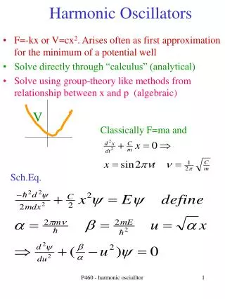
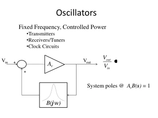
Oscillators An oscillator is an electronic device which converts DC power from the supply into AC power in the load without the application of an external input signal. The essential components of the oscillator are: Tank circuit, Transistor amplifier, and Feedback circuit Tank circuit Amplifier and Feedback diagram
Classification of Oscillators Depending upon the method of producing oscillations. (a) Feedback oscillators (b) Negative resistance oscillators Depending upon nature of generated waveform (a) Sinusoidal or harmonic oscillators (b) Non-sinusoidal or relaxation oscillators Both sinusoidal and relaxation oscillators may be negative resistance and feedback type. Depending upon the frequency of generated voltage. (a) Audio frequency (AF) oscillator (b) Radio frequency (RF) oscillator (c) very high frequency (VHF) oscillators (d) ultrahigh frequency (UHF) oscillators (e)Microwave oscillators
Fundamental Principle of Oscillators In oscillator, a negative resistance is provided to compensate for the losses in the circuit. In a feedback oscillator, external positive feedback sufficient to make the overall gain infinity, provides the negative resistance required to overcome the natural damping of the oscillations. In a negative resistance oscillator internal positive feedback is present and serves to provide the required negative resistance. In an oscillator no external signal is applied. The initial signal to trigger the oscillations is ordinarily supplied by the noise voltage. This noise voltage originates when the power supply is switched on. Since the frequency spectrum of noise is very wide, it always possesses a component voltage at a frequency that is correct for the oscillator operation.
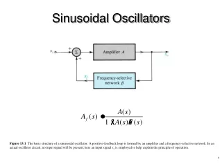
Feedback oscillators The basic requirements of a feedback oscillator are: An amplifier with positive feedback to provide negative resistance in the circuit. Some circuit non-linearity to define amplitude of oscillators. A frequency determining network to produce oscillations at a desired frequency. Dc power supply to act as energy source.
Tuned collector oscillator The basic circuit of a tuned collector oscillator is shown in figure. It is called the tuned-collector oscillator, because the tuned circuit is connected to the collector. The tuned circuit, constituted by the capacitor C and transformer primary coiL, forms the load impedance and determines the frequency of oscillation.
Hartley oscillator Hartley oscillator is an electronic oscillator circuit that uses an inductor and a capacitor in parallel to determine the frequency. It is used in radio receiver as a local oscillator because (i) It is easy to tune (ii) It’s adaptability to a wide range of frequencies • Hartley Oscillator is generally of two types: • Series fed oscillator • 2. Parallel or shunt fed Hartley oscillator
Series Fed Hartley oscillator In series fed Hartley oscillator, the junction of two inductors of the tuned circuit is directly connected to Vcc and one end of the LC circuit is connected to the collector of the transistor. The lower portion of the tank coil is inductively coupled to the upper portion.
Shunt fed Hartley oscillator Shunt fed Hartley oscillator uses a transistor in CE configuration, in which the collector current is divided into two parallel paths. One branch connects the collector to the Vcc through RFC and provides the path for DC keeping the AC out. The other branch connects the collector to LC tank through a capacitor and provides the path for AC keeping the DC out.
AC equivalent circuit of Hartley oscillator (a) (b) The frequency of oscillation is given by,
From fig. (b), we have Let the currents I1, I2 and I3 be non-zero. Applying Kirchhoff’s voltage law to loop (1), we get Similarly, applying Kirchhoff’s voltage law to loop (2) and (3), we get and
Rearranging the above eqns. We get For non-zero I1, I2, I3, the determinant of above three eqns. must be zero. At frequency of oscillation,
Taking real part of the equation equal to zero, we get Since hre < < 1and putting hie hoe – hfe hre = ∆he, the above equation becomes, In general, > > 4 ∆ he Therefore, This is the equation for sustained oscillations.
Taking imaginary part of the equation equal to zero, we get This is the frequency of oscillations of Hartley oscillator.
Colpitts LC-Tuned Oscillator Feedback amplifier with inductor L and capacitors C1 and C2 in feedback network. Feedback is frequency dependent. Aim to adjust components to get positive feedback and oscillation. Output taken at collector Vo. No input needed, noise at oscillation frequency o is picked up and amplified. RB1 and RB2 are biasing resistors. RFC is RF Choke (inductor) to allow dc current flow for transistor biasing, but to block ac current flow to ac ground. Simplified circuit shown at midband frequencies where large emitter bypass capacitor CE and base capacitor CB are shorts and transistor capacitances (C and C) are opens. CB V0 CE Vi V0 Vi
Colpitts LC-Tuned Oscillator Voltage across C2 is just V Neglecting input current to transistor (I 0), Then, output voltage Vo is KCL at output node (C) Setting s = j AC equivalent circuit Assuming oscillations have started, then V≠ 0 and Vo ≠ 0, so sC2V V0 Iπ≈ 0 sC2V
Colpitts LC-Tuned Oscillator To get oscillations, both the real and imaginary parts of this equation must be set equal to zero. From the imaginary part we get the expression for the oscillation frequency From the real part, we get the condition on the ratio of C2/C1
Colpitts LC-Tuned Oscillator Given: Design oscillator at 150 MHz Transistor gm = 100 mA/V, R = 0.5 K Design: Select L= 50 nH, then calculate C2, andthen C1 Example
Phase Shift Oscillator Based on op amp using inverting input Combination of R’s and C’s in feedback loop so get additional phase shift. Target 180o to get oscillation. Analysis assumes op amp is ideal. Rf If IC3 IC2 IC1 V2 V1 VX C C C V0 IR1 R R IR2
Phase Shift Oscillator If Rf IC3 IC2 IC1 V2 V1 VX C C C V0 R R IR1 IR2 Example Oscillator specifications: o=1x10⁶ rad/s Note: We get 180o phase shift from op amp since input is to inverting terminal and another 180o from the RC ladder.
WIEN BRIDGE OSCILLATOR Wien bridge oscillator is a two stage amplifier. The first stage is CE amplifier and the second stage is CC amplifier. The output of the second stage is fed back to the first stage through feed back network consisting of R1C1 in series and R2C2 in parallel. It is advantageous over phase shift oscillator as its frequency can be varied over a frequency range of 10:1.
The ratio of output voltage of the network to the input voltage is given by
If the imaginary term vanishes, the phase shift will be zero i.e. Therefore, frequency of oscillation is, Also, we have Hence the oscillations will be sustained if the amplifier has a gain just exceeding 3.