Download
1 / 36
360 likes | 495 Views
This lecture outlines the essential steps in designing a single-cycle datapath for a processor. We revisit the broader context of computer architecture, focusing on the classic components and the performance metrics determining a machine's efficiency. Key topics include datapath design for register-register operations, logical operations with immediate values, load/store actions, and branch/jump operations. The session emphasizes the importance of instruction set architecture, control signals, and critical path analysis, offering insights into real-world applications and assignments.

E N D
CpE242Computer Architecture and EngineeringDesigning a Single Cycle Datapath
Outline of Today’s Lecture • Recap and Introduction (5 minutes) • Where are we with respect to the BIG picture? (15 minutes) • The Steps of Designing a Processor (10 minutes) • Datapath and timing for Reg-Reg Operations (15 minutes) • Datapath for Logical Operations with Immediate (5 minutes) • Datapath for Load and Store Operations (10 minutes) • Datapath for Branch and Jump Operations (10 minutes) • Assignment #3
Processor Input Control Memory Datapath Output The Big Picture: Where are We Now? • The Five Classic Components of a Computer • Today’s Topic: Datapath Design
The Big Picture: The Performance Perspective • Performance of a machine was determined by: • Instruction count • Clock cycle time • Clock cycles per instruction • Processor design (datapath and control) will determine: • Clock cycle time • Clock cycles per instruction • In the next two lectures: • Single cycle processor: • Advantage: One clock cycle per instruction • Disadvantage: long cycle time
31 26 21 16 11 6 0 op rs rt rd shamt funct 6 bits 5 bits 5 bits 5 bits 5 bits 6 bits 31 26 21 16 0 immediate op rs rt 6 bits 5 bits 5 bits 16 bits 31 26 0 op target address 6 bits 26 bits The MIPS Instruction Formats • All MIPS instructions are 32 bits long. The three instruction formats: • R-type • I-type • J-type • The different fields are: • op: operation of the instruction • rs, rt, rd: the source and destination register specifiers • shamt: shift amount • funct: selects the variant of the operation in the “op” field • address / immediate: address offset or immediate value • target address: target address of the jump instruction
31 26 21 16 11 6 0 op rs rt rd shamt funct 6 bits 5 bits 5 bits 5 bits 5 bits 6 bits 31 26 21 16 0 op rs rt immediate 6 bits 5 bits 5 bits 16 bits 31 26 0 op target address 6 bits 26 bits The MIPS Subset • ADD and subtract • add rd, rs, rt • sub rd, rs, rt • OR Immediate: • ori rt, rs, imm16 • LOAD and STORE • lw rt, rs, imm16 • sw rt, rs, imm16 • BRANCH: • beq rs, rt, imm16 • JUMP: • j target
ALU An Abstract View of the Implementation Clk PC Instruction Address Ideal Instruction Memory Instruction Rd Rs Rt Imm 5 5 5 16 Data Address 32 Rw Ra Rb 32 Ideal Data Memory 32 DataOut 32 32-bit Registers Data In Clk Clk 32
. . . . . . . . . . . . Clocking Methodology Clk Setup Hold Setup Hold • All storage elements are clocked by the same clock edge • Cycle Time = CLK-to-Q + Longest Delay Path + Setup + Clock Skew Don’t Care
ALU An Abstract View of the Critical Path • Register file and ideal memory: • The CLK input is a factor ONLY during write operation • During read operation, behave as combinational logic: • Address valid => Output valid after “access time.” Critical Path (Load Operation) = PC’s Clk-to-Q + Instruction Memory’s Access Time + Register File’s Access Time + ALU to Perform a 32-bit Add + Data Memory Access Time + Setup Time for Register File Write + Clock Skew Clk PC Instruction Address Ideal Instruction Memory Instruction Rd Rs Rt Imm 5 5 5 16 Data Address 32 Rw Ra Rb 32 Ideal Data Memory 32 DataOut 32 32-bit Registers Data In Clk Clk 32
The Steps of Designing a Processor • Instruction Set Architecture => Register Transfer Language • Register Transfer Language => Datapath Design • Datapath components • Datapath interconnect • Datapath components => Control signals • Control signals => Control logic => Control Unit Design
RTL: The ADD Instruction • add rd, rs, rt • mem[PC] Fetch the instruction from memory • R[rd] <- R[rs] + R[rt] The ADD operation • PC <- PC + 4 Calculate the next instruction’s address
RTL: The Load Instruction • lw rt, rs, imm16 • mem[PC] Fetch the instruction from memory • Addr <- R[rs] + SignExt(imm16) Calculate the memory address • R[rt] <- Mem[Addr] Load the data into the register • PC <- PC + 4 Calculate the next instruction’s address
Combinational Logic Elements CarryIn A 32 • Adder • MUX • ALU Sum Adder 32 B Carry 32 Select A 32 MUX Y 32 B 32 OP A 32 ALU Result 32 B Zero 32
Storage Element: Register Write Enable • Register • Similar to the D Flip Flop except • N-bit input and output • Write Enable input • Write Enable: • 0: Data Out will not change • 1: Data Out will become Data In Data In Data Out N N Clk
Storage Element: Register File RW RA RB Write Enable 5 5 5 • Register File consists of 32 registers: • Two 32-bit output busses: busA and busB • One 32-bit input bus: busW • Register is selected by: • RA selects the register to put on busA • RB selects the register to put on busB • RW selects the register to be writtenvia busW when Write Enable is 1 • Clock input (CLK) • The CLK input is a factor ONLY during write operation • During read operation, behaves as a combinational logic block: RA or RB valid => busA or busB valid after “access time.” busA busW 32 32 32-bit Registers 32 busB Clk 32
Write Enable Address Data In DataOut 32 32 Clk Storage Element: Idealized Memory • Memory (idealized) • One input bus: Data In • One output bus: Data Out • Memory word is selected by: • Address selects the word to put on Data Out • Write Enable = 1: address selects the memorymemory word to be written via the Data In bus • Clock input (CLK) • The CLK input is a factor ONLY during write operation • During read operation, behaves as a combinational logic block: • Address valid => Data Out valid after “access time.”
PC Clk Next Address Logic Address Instruction Memory Overview of the Instruction Fetch Unit • The common RTL operations • Fetch the Instruction: mem[PC] • Update the program counter: • Sequential Code: PC <- PC + 4 • Branch and Jump PC <- “something else” Instruction Word 32
31 26 21 16 11 6 0 op rs rt rd shamt funct 6 bits 5 bits 5 bits 5 bits 5 bits 6 bits RTL: The ADD Instruction • add rd, rs, rt • mem[PC] Fetch the instruction from memory • R[rd] <- R[rs] + R[rt] The actual operation • PC <- PC + 4 Calculate the next instruction’s address
31 26 21 16 11 6 0 op rs rt rd shamt funct 6 bits 5 bits 5 bits 5 bits 5 bits 6 bits RTL: The Subtract Instruction • sub rd, rs, rt • mem[PC] Fetch the instruction from memory • R[rd] <- R[rs] - R[rt] The actual operation • PC <- PC + 4 Calculate the next instruction’s address
31 26 21 16 11 6 0 op rs rt rd shamt funct 6 bits 5 bits 5 bits 5 bits 5 bits 6 bits Datapath for Register-Register Operations • R[rd] <- R[rs] op R[rt] Example: add rd, rs, rt • Ra, Rb, and Rw comes from instruction’s rs, rt, and rd fields • ALUctr and RegWr: control logic after decoding the instruction Rd Rs Rt ALUctr RegWr 5 5 5 busA Rw Ra Rb busW 32 32 32-bit Registers Result ALU 32 32 busB Clk 32
Register-Register Timing Clk Clk-to-Q Old Value New Value PC Instruction Memory Access Time Rs, Rt, Rd, Op, Func Old Value New Value Delay through Control Logic ALUctr Old Value New Value RegWr Old Value New Value Register File Access Time busA, B Old Value New Value ALU Delay busW Old Value New Value Rd Rs Rt ALUctr Register Write Occurs Here RegWr 5 5 5 busA Rw Ra Rb busW 32 32 32-bit Registers Result ALU 32 32 busB Clk 32
31 26 21 16 0 op rs rt immediate 6 bits 5 bits 5 bits 16 bits 31 16 15 0 immediate 0 0 0 0 0 0 0 0 0 0 0 0 0 0 0 0 16 bits 16 bits RTL: The OR Immediate Instruction • ori rt, rs, imm16 • mem[PC] Fetch the instruction from memory • R[rt] <- R[rs] or ZeroExt(imm16) The OR operation • PC <- PC + 4 Calculate the next instruction’s address
11 31 26 21 16 0 op rs rt immediate 6 bits 5 bits 5 bits 16 bits rd Datapath for Logical Operations with Immediate • R[rt] <- R[rs] op ZeroExt[imm16]] Example: ori rt, rs, imm16 Rd Rt RegDst Mux Don’t Care (Rt) Rs ALUctr RegWr 5 5 5 busA Rw Ra Rb busW 32 Result 32 32-bit Registers ALU 32 32 busB Clk 32 Mux ZeroExt imm16 32 16 ALUSrc
31 26 21 16 0 op rs rt immediate 6 bits 5 bits 5 bits 16 bits 31 16 15 0 0 immediate 0 0 0 0 0 0 0 0 0 0 0 0 0 0 0 0 16 bits 16 bits 31 16 15 0 1 1 1 1 1 1 1 1 1 1 1 1 1 1 1 1 1 immediate 16 bits 16 bits RTL: The Load Instruction • lw rt, rs, imm16 • mem[PC] Fetch the instruction from memory • Addr <- R[rs] + SignExt(imm16) Calculate the memory address R[rt] <- Mem[Addr] Load the data into the register • PC <- PC + 4 Calculate the next instruction’s address SignExt operation
11 31 26 21 16 0 op rs rt immediate 6 bits 5 bits 5 bits 16 bits rd Datapath for Load Operations • R[rt] <- Mem[R[rs] + SignExt[imm16]] Example: lw rt, rs, imm16 Rd Rt RegDst Mux Don’t Care (Rt) Rs ALUctr RegWr 5 5 5 MemtoReg busA Rw Ra Rb busW 32 32 32-bit Registers ALU 32 32 Mux busB Clk MemWr 32 32 Mux WrEn Adr Data In Data Memory Extender 32 imm16 32 16 Clk ALUSrc ExtOp
31 26 21 16 0 op rs rt immediate 6 bits 5 bits 5 bits 16 bits RTL: The Store Instruction • sw rt, rs, imm16 • mem[PC] Fetch the instruction from memory • Addr <- R[rs] + SignExt(imm16) Calculate the memory address • Mem[Addr] <- R[rt] Store the register into memory • PC <- PC + 4 Calculate the next instruction’s address
31 26 21 16 0 op rs rt immediate 6 bits 5 bits 5 bits 16 bits Datapath for Store Operations • Mem[R[rs] + SignExt[imm16] <- R[rt]] Example: sw rt, rs, imm16 Rd Rt RegDst Mux Rs Rt ALUctr RegWr 5 5 5 MemWr MemtoReg busA Rw Ra Rb busW 32 32 32-bit Registers ALU 32 32 Mux busB Clk 32 32 Mux WrEn Adr Data In 32 Data Memory Extender imm16 32 16 Clk ALUSrc ExtOp
31 26 21 16 0 op rs rt immediate 6 bits 5 bits 5 bits 16 bits RTL: The Branch Instruction • beq rs, rt, imm16 • mem[PC] Fetch the instruction from memory • Cond <- R[rs] - R[rt] Calculate the branch condition • if (COND eq 0) Calculate the next instruction’s address PC <- PC + 4 + ( SignExt(imm16) x 4 ) else PC <- PC + 4
31 26 21 16 0 op rs rt immediate 6 bits 5 bits 5 bits 16 bits PC Next Address Logic Datapath for Branch Operations • beq rs, rt, imm16 We need to compare Rs and Rt! Clk Rd Rt Branch RegDst Mux Rs Rt ALUctr imm16 RegWr 5 5 5 busA 16 Rw Ra Rb busW 32 32 32-bit Registers ALU 32 Zero To Instruction Memory busB Clk 32 Mux Extender 32 imm16 16 ALUSrc ExtOp
Binary Arithmetics for the Next Address • In theory, the PC is a 32-bit byte address into the instruction memory: • Sequential operation: PC<31:0> = PC<31:0> + 4 • Branch operation: PC<31:0> = PC<31:0> + 4 + SignExt[Imm16] * 4 • The magic number “4” always comes up because: • The 32-bit PC is a byte address • And all our instructions are 4 bytes (32 bits) long • In other words: • The 2 LSBs of the 32-bit PC are always zeros • There is no reason to have hardware to keep the 2 LSBs • In practice, we can simply the hardware by using a 30-bit PC<31:2>: • Sequential operation: PC<31:2> = PC<31:2> + 1 • Branch operation: PC<31:2> = PC<31:2> + 1 + SignExt[Imm16] • In either case: Instruction Memory Address = PC<31:2> concat “00”
PC 0 Adder Mux 1 Adder Clk Next Address Logic: Expensive and Fast Solution • Using a 30-bit PC: • Sequential operation: PC<31:2> = PC<31:2> + 1 • Branch operation: PC<31:2> = PC<31:2> + 1 + SignExt[Imm16] • In either case: Instruction Memory Address = PC<31:2> concat “00” 30 Addr<31:2> 30 Addr<1:0> “00” 30 Instruction Memory 30 “1” 32 30 SignExt 30 imm16 16 Instruction<15:0> Instruction<31:0> Branch Zero
PC 0 Adder Mux Clk 1 Next Address Logic: Cheap and Slow Solution • Why is this slow? • Cannot start the address add until Zero (output of ALU) is valid • Does it matter that this is slow in the overall scheme of things? • Probably not here. Critical path is the load operation. 30 Addr<31:2> 30 “1” Addr<1:0> “00” Carry In Instruction Memory “0” 30 32 SignExt imm16 30 30 16 Instruction<15:0> Instruction<31:0> Branch Zero
31 26 0 op target address 6 bits 26 bits RTL: The Jump Instruction • j target • mem[PC] Fetch the instruction from memory • PC<31:2> <- PC<31:28> concat target<25:0> Calculate the next instruction’s address
1 Mux PC 0 0 Adder Mux 1 Adder Clk Instruction Fetch Unit • j target • PC<31:2> <- PC<31:29> concat target<25:0> 30 Addr<31:2> 30 PC<31:28> Addr<1:0> “00” 4 Target Instruction Memory 30 Instruction<25:0> 26 30 32 30 “1” Jump Instruction<31:0> 30 SignExt 30 imm16 16 Instruction<15:0> Branch equal Zero
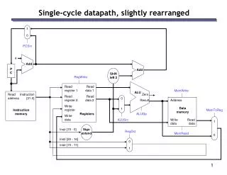
Putting it All Together: A Single Cycle Datapath • We have everything except control signals (underline) Instruction<31:0> Branch Instruction Fetch Unit Jump Rd Rt <21:25> <16:20> <11:15> <0:15> Clk RegDst 1 0 Mux Rt Rs Rd Imm16 Rs Rt RegWr ALUctr 5 5 5 MemtoReg busA Zero MemWr Rw Ra Rb busW 32 32 32-bit Registers 0 ALU 32 busB 32 0 Clk Mux 32 Mux 32 1 WrEn Adr 1 Data In 32 Data Memory Extender imm16 32 16 Clk ALUSrc ExtOp
Assignment #3Text, Ch.5 Exercises section,problems 5.8, 5.10, 5.13, and 5.28Due Sept. 29, 2009