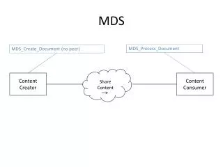
MDS COMMISSIONING
MDS COMMISSIONING. COMMISSIONING. Address Setting. DIP switch S2. A-series outdoor unit PCB. K1, K2 Button. Press K2 for 5 seconds to enter parameter set mode LCD display “- - - -” Enter the password, 0755 Set the no. of indoor units. DIP switch S1. COMMISSIONING. ON (1)


MDS COMMISSIONING
E N D
Presentation Transcript
COMMISSIONING Address Setting DIP switch S2 A-series outdoor unit PCB K1, K2 Button • Press K2 for 5 seconds to enter parameter set mode • LCD display “- - - -” • Enter the password, 0755 • Set the no. of indoor units DIP switch S1
COMMISSIONING ON (1) OFF (0) ON (1) OFF (0) S2 S1 1 2 3 4 5 6 7 8 1 2 3 4 5 6 7 Reserved Capacity Outdoor Address Reserved EXV Initial Opening A-series outdoor unit PCB
COMMISSIONING Address Setting B-series outdoor unit PCB DIP switch S1,S2
COMMISSIONING B-series outdoor unit PCB S1 S2 S3 ON (1) OFF (0) 1 2 3 4 1 2 3 4 5 6 7 8 1 2 3 4 5 6 7 8 Outdoor unit capacity No. of indoor units Outdoor address EXV initial opening Cooling / Heating Master / Slave MDS _A/B
COMMISSIONING Address Setting Indoor unit PCB DIP switch S2
COMMISSIONING Indoor unit PCB ON (1) OFF (0) ON (1) OFF (0) 1 2 3 4 5 6 1 2 3 4 5 6 1 2 3 4 5 6 7 8 Auxiliary Heater 1 Auxiliary Heater 2 Reserved Address Capacity Model Water Pump
COMMISSIONING LCD Display Receiver ON / OFF Temperature Up / Down Fan Mode Heater / Swing Sleep Timer Setting SLM Controller
COMMISSIONING Handset Setting SLM Controller Real Timer Setting Press “CLK” Day Setting CLK * Press “Δ” or “▽” to change the day setting (Monday ~ Sunday) Press “CLK” again to confirm *Note: If no action within 5s, it will return to main page
COMMISSIONING Handset Setting SLM Controller Real Timer Setting After day setting is confirmed LCD real time blink CLK * Press “Δ” to increase 1 hour Press “▽” to increase 1 minute Press “CLK” again to confirm *Note: If no action within 5s, it will return to main page
COMMISSIONING Handset Setting SLM Controller • DIP1 – Temperature Unit Setting • ON - °F • OFF - °C • DIP2 – Auto Start Setting • ON - Available • OFF - N/A DIP switch
COMMISSIONING Test Run • Check the power supply between outdoor unit and switch board. • 1. 220V power supply (L / N) • 2. 380V power supply • – make sure the phase sequence are correct, L1(R) L2(S) L3(T) • Outdoor unit powered ON 6 hours in advance to preheat the crankcase heater. • If main power is turned OFF for a long time, the system cannot run immediately after power resume. (Need to wait for 2.5 hours)
COMMISSIONING Test Run Continue… • Indoor unit checking:- • 1. Check the power supply wiring and signal wiring in each indoor unit. • 2. If the signal wire and power wire are cross-connected, all PCB will burn. • 3. The signal wires must be in different colour for different terminal in order to avoid misconnection of polarity. • 4. Check the address setting of the indoor unit:- • – Make sure the address settings are correct. • – Each indoor unit should have different address. • Outdoor unit checking:- • 1. Check the no. of indoor unit settings are correct. • 2. Make sure the capacity settings are correct. • 3. Make sure the Master and Slave unit setting are correct (if applicable).