Download
1 / 24
240 likes | 432 Views
The 3 MeV H - Test Stand at CERN - The first part of the SPL - H. Haseroth on behalf of the SPL Study Group (Prepared by Carlo Rossi). The 3 MeV H - Test Stand at CERN. OUTLINE The long term SPL project : motivation for a 3 MeV Test Stand.

E N D
The 3 MeV H- Test Stand at CERN - The first part of the SPL - H. Haseroth on behalf of theSPL Study Group (Prepared by Carlo Rossi) H. Haseroth July 26 – August 1, 2004 NuFact04, Osaka
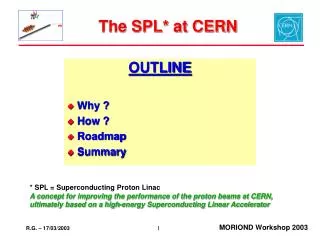
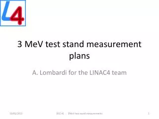
The 3 MeV H- Test Stand at CERN OUTLINE • The long term SPL project: motivation for a 3 MeV Test Stand. • The intermediate Linac4 phase: a valuable improvement of the CERN proton accelerator complex. • The 3 MeV Test Stand: a short term study tool and the future SPL Front End. • Status and Planning. H. Haseroth July 26 – August 1, 2004 NuFact04, Osaka
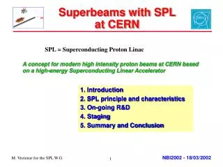
SPL: a long term project A multi-MW superconducting linac could simultaneously satisfy the needs of many users. Especially relevant are the potential applications* for: • Radio-active ions • Neutrinos: super-beam/beta-beam/neutrino factory • LHC: potential to increase the brightness and intensity beyond the ultimate beam. The challenge for high beam power is mostly coming from the control of beam halo. The control starts from the low energy end. A test bench for beam dynamics studies (including beam halo) is a must. *Debated at the workshop on “Physics with a multiMW Proton Source”, CERN, May 25-27, http://physicsatmwatt.web.cern.ch/physicsatmwatt/ H. Haseroth July 26 – August 1, 2004 NuFact04, Osaka
SPL block diagram (CDR 1) Linac 4:up-to-date design Superconducting linac:CDR 1 H. Haseroth July 26 – August 1, 2004 NuFact04, Osaka
Linac4: a mid-term phase Linac4 is the room-temperature section of the SPL (extended to 160 MeV), intended to upgrade the injection into the PS Booster. It allows for a significant performance improvement for the present users like LHC and ISOLDE, at a limited cost. H. Haseroth July 26 – August 1, 2004 NuFact04, Osaka
Linac4 parameters Linac4 could be laterused as front-end of the SPL: its RF structures are designed to operate at the full SPL duty cycle. • Relaxed parameters • Space and infrastructure available in the PS South Hall • RF from LEP (klystrons, waveguides, etc. - already in stock) H. Haseroth July 26 – August 1, 2004 NuFact04, Osaka
95keV 3MeV 40MeV 90MeV 160MeV H- RFQ MEBT DTL CCDTL SCL IPHI RFQ 6 m 1 klystron chopping line 3.6 m Drift Tube Linac 352 MHz 16.7 m 3 tanks 5 klystrons Cell-Coupled Drift Tube L. 352 MHz 30.1 m 33 tanks 6 klystrons Side Coupled Linac 704 MHz 28.1 m 20 tanks 5 klystrons 30 mA, 0.1% duty Final Energy 160 MeV, factor 2 in bg2 w.r.t. present 50 MeV Linac2 Total Linac4: 86.5 m , 17 klystrons Linac4 layout H. Haseroth July 26 – August 1, 2004 NuFact04, Osaka
Installation Layout 3 MeV Test Place H. Haseroth July 26 – August 1, 2004 NuFact04, Osaka
The 3 MeV Test Stand Specific Components Chopper structure H- ECR ion source IPHI RFQ Bunching cavities HV pulsed power supplies for the LEP klystrons Beam Shape and Halo Monitor H. Haseroth July 26 – August 1, 2004 NuFact04, Osaka
The 3 MeV Test Stand • Beam dynamics at low energy. • Development of the Chopper line: • to generate the required time structure of the beam • to clean the beam from halo • to match it to the subsequent RF structures. H. Haseroth July 26 – August 1, 2004 NuFact04, Osaka
The H- ECR Source Tests on the prototype source are under way. Design work will be carried out during the rest of 2004 and 2005. The final source is not expected before 2007. H. Haseroth July 26 – August 1, 2004 NuFact04, Osaka
The RFQ TheIPHI (“Injecteur de Protons de Haute Intensité”) RFQ is at the core of the 3 MeV Test Place. Itis being developed in France within the IPHI collaboration between CEA and CNRS which CERN has recently joined . RF power is generated by a LEP klystron (352.21 MHz, 1 MW CW) that will be operated in pulsed mode, by means of dedicated power supplies expressly developed by a collaboration between GSI and CERN. H. Haseroth July 26 – August 1, 2004 NuFact04, Osaka
HV Pulsed Power Supplies for the LEP klystron CERN and GSI are formalizing an agreement for the development of the power supplies based on common requirements (Linac4 @ CERN and FAIR injector @ GSI). First power supply to be delivered before end 2005, second before end 2006. H. Haseroth July 26 – August 1, 2004 NuFact04, Osaka
The Chopper line General guidelines Compact design 3 m length Dynamic range 20 – 60 mA Small e growth ez = const erout = 1.17 erin Tolerant to alignment errors Good vacuum ~10-8 Torr H. Haseroth July 26 – August 1, 2004 NuFact04, Osaka
Beam Dynamics in the Chopper Line The chopper line is designed transversely as five FODO periods, while longitudinally three RF cavities match the beam from the RFQ output to the (future) DTL input. Chopper structure Chopper structure RFQ output DTL input Buncher cavity Buncher cavity Buncher cavity H. Haseroth July 26 – August 1, 2004 NuFact04, Osaka
Beam Dump – Side view Water ~ 100 mm Un-chopped beam a 3 bunches are dumped 5 bunches are transmitted Vacuum flange Water a = 10 degrees Beam Chopping (1) A beam dump has been designed to intercept the deviated beam 1 m downstream from the last chopper structure (radial separation between the beam centers: 1.5 cm) H. Haseroth July 26 – August 1, 2004 NuFact04, Osaka
Beam Chopping (2) 2 ns rise/fall time is required for bunch selectivity (352 MHz beam structure), ±500V between the deflecting plates to get the required separation at the dump. Double meander structure on Alumina substrate The prototype of the RF amplifier is under test The first chopper structure is under fabrication Pulse length: 8ns to 2ms Rep. rate (max): 45 MHz H. Haseroth July 26 – August 1, 2004 NuFact04, Osaka
Longitudinal matching The longitudinal matching is performed by 3 RF cavities working at 352 MHz: two with 30 mm aperture (B30), and one with 40 mm aperture (B40) placed in the chopping region. B30 B40 Frequency (MHz) 352.0 352.0 Gap length (mm) 14.0 14.0 Q value 25000 24000 Shunt impedance (MW) 1.28 0.64 R/Q 52.2 27.1 Nominal voltage (kV) 140 100 Dissipated power (kW peak) 16 16.2 Kilpatrick factor 1.22 1.16 The electromagnetic and mechanical design has been completed for the whole set of RF cavities. The construction phase for the first B30 cavity is starting and will be completed within the end of 2004. H. Haseroth July 26 – August 1, 2004 NuFact04, Osaka
The Beam Shape & Halo Monitor Longitudinal measurement Measure residual H- in (not completely) chopped buckets with a sensitivity of ~ 1000 ions, in the vicinity of full bunches (108 ions). Detector must be turned ON/OFF within 1 ns, gating ratio 1:106 Transverse measurement Halo diagnostics: Beam core: d=1 cm, 108 H- /bunch/ cm2 Beam halo: d=4 cm, 103H- /bunch/ cm2 Active area of detector 4 × 4 cm Dynamic range: 1:106 by integrating over several buckets All components have been delivered. The vacuum chamber is being designed. The detector will be commissioned during the first months of 2005. H. Haseroth July 26 – August 1, 2004 NuFact04, Osaka
Measurement Program The 3 MeV test place will be used to commission the different components of the line and perform “conventional” measurements on the beam, in order to scan the full dynamic range of the system. Three sets of measurements have particular relevance: Validation of the Chopper principle and hardware Characterize the separation capability (on/off) of the chopper line (chopper voltage) and its time selectivity (rise and fall time). Beam matching properties of the line Measure longitudinal and transverse emittance (expected accuracy within 10%) within different beam conditions. Halo studies Optimize the collimation system by characterizing the beam halo in shape and intensity. H. Haseroth July 26 – August 1, 2004 NuFact04, Osaka
Planning of the Project Test of Linac4 RF structures is possible Linac4 approval Decision on SPL H. Haseroth July 26 – August 1, 2004 NuFact04, Osaka
Status of the Project • The European Union is supporting beam dynamics studies and RF system developments in the frame of the HIPPI “Joint Research Activity”. • The design of the 3 MeV Test Stand is almost completed. Still missing: • study of the beam current monitor • design of the vacuum chamber (short sections between major components) • The design of the major components will be completed in 2004. • The start of Linac4 construction in 2006 has been included by the CERN DG among the strategic priorities of the laboratory The 3 MeV Test Stand is being designed to become the Linac4 Front End. H. Haseroth July 26 – August 1, 2004 NuFact04, Osaka
CDR 2 3 MeV test place ready RF test place ready Linac4 approval SPL approval LHC upgrade The full picture … H. Haseroth July 26 – August 1, 2004 NuFact04, Osaka
Thank you and Carlo Rossi for the preparation of this presentation H. Haseroth July 26 – August 1, 2004 NuFact04, Osaka