5-Bit Current Steering DAC
5-Bit Current Steering DAC. Salih Kilic Jeff Lee James Li Brian Miller Advisor: Dave Parent May 17, 2004. Agenda. Abstract Introduction Why Simple Theory Back Ground information (Lit Review) Summary of Results Project (Experimental) Details Results Cost Analysis Conclusions.

5-Bit Current Steering DAC
E N D
Presentation Transcript
5-Bit Current Steering DAC Salih Kilic Jeff Lee James Li Brian Miller Advisor: Dave Parent May 17, 2004
Agenda • Abstract • Introduction • Why • Simple Theory • Back Ground information (Lit Review) • Summary of Results • Project (Experimental) Details • Results • Cost Analysis • Conclusions
Abstract • We designed a 5-Bit current steering DAC that operated at 150 MHz and occupied an area of 560 x 590mm^2
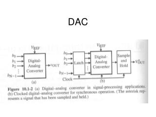
Introduction • CMOS D/A converters have the advantage of low power, low cost, and are compatible with external CMOS circuitry. • CMOS D/A are essential components in most consumer video systems. • Create a current that is proportional to a digital input.
Project Summary • Our DAC consisted of 3 blocks • Row/Column Decoder • D-Flip Flops • Current Cell Matrix
Row/Column Decoder • We converted binary into thermometer code. • Ensures only 1 bit changes per state. • Multiple bits changing simultaneously causes BIG glitches! • Use of Row and Column keeps layout compact.
D-Flip Flops • Ensures synchronization of inputs • Prevents glitches
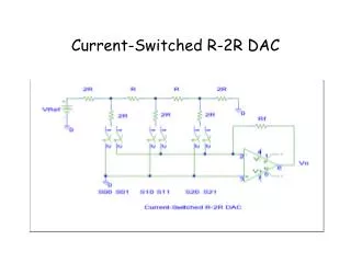
Current Matrix • Decoding Logic • Decides which current cells to turn on. • Current Mirror • Mirrored 247.9um to 32 different current cells. • Current Switches • Linked our decoding logic to our current sources.
Current, Voltage, Power • Average current: 6.3mA • Average Voltage: 2.5V • Area = 560um x 590um = 330,400um^2 • Power Density = (Iavg x Vavg)/Area = 4.76W/cm^2
Longest Path Calculations Note: All widths are in microns and capacitances in fF
Cost Analysis • Estimate how much time you spent on each phase of the project • verifying logic : 2 weeks • verifying timing : 3 weeks • layout : 2 week
Lessons Learned • Don’t route in poly • Make Flip Flop layout compact • Start Early • Go to office hours
Summary • Our DAC functions at 150MHz and occupies an area of 560um by 590 um with power density of 4.76W/cm^2. • Future DAC’s will be more compact and able to function at higher frequencies with less power consumption
Acknowledgements • Thanks to Dr. Parent for direction and guidance • Thanks to Cadence Design Systems for the VLSI lab • Thanks to Synopsys for Software donation