Download
1 / 24
310 likes | 814 Views
5 bit binary to 1 of 32 select decoder (to be used in 5 bit DAC). Dan Brisco, Steve Corriveau Advisor: Dave Parent 14 May 2004. Agenda. Abstract Introduction Why Simple Theory Back Ground information (Lit Review) Summary of Results Project (Experimental) Details Results Conclusions.

E N D
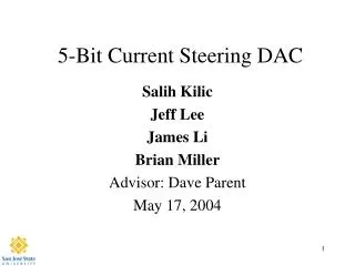
5 bit binary to 1 of 32 select decoder (to be used in 5 bit DAC) Dan Brisco, Steve Corriveau Advisor: Dave Parent 14 May 2004
Agenda • Abstract • Introduction • Why • Simple Theory • Back Ground information (Lit Review) • Summary of Results • Project (Experimental) Details • Results • Conclusions
Abstract • We designed the circuit to operate at 200MHz with room for extra logic stages for the analog conversion yet to be added. • We needed to assure that only one output was selected at a time without having to clocking the outputs. • Our design is 171.6um X 534.6um and uses 1.02mW of power.
Introduction • A 5 bit DAC as IP will be very useful for DSP projects in the future. • Design a decoder with symmetric rise and fall times and minimal settling errors. • We have laid out our circuit utilizing the best timing path even though we calculated and tested it for the worst case.
Previous Work • 2003 Gonzalez, Yu & Korbes. 6-bit Analog to Digital / Digital to Analog Converter. • 1997 Baker, Li & Boyce. CMOS Circuit Design, Layout, and Simulation. • 1987 Allen & Holberg. CMOS Analog Circuit Design. • 2003 Kang & Leblebici. CMOS Digital Integrated Circuits.
Project Summary • A 6 bit DAC was presented last year that had a non-linear output with possible reasons being. • Timing issues • More than one output being selected • Settling time causing selection of the wrong output. • Our design has 5 logic levels. • We designed for 10 to allow for the analog conversion later.
Project Details • The 5 to 32 bit decoder utilized 4 base cells. • Nand3, Inverter and Nand2 were used to build a Nand5. • Nand2 & 3 and Inv cell heights are 15.9um. • Mux based DFF with nRST was used to hold the input logic and fan out the signals to 32 Nand5’s for decoding. • DFF cell height is 36.0um. • Nand5 cell height is 29.4um. • The whole design is 171.6um X 534.6um.
Longest Path Calculations Note: All widths are in microns and capacitances in fF
Mux DFF with nRST CLK nQ nRST D Q
Cost Analysis • We estimate the time we spent on each phase of the project to be, • verifying logic – 16hrs • verifying timing – 16hrs • Layout – 32hrs • post extracted timing – 4hrs • Log-in/out – 8hrs
Conclusions • This project provided a good basis for IC design. • We looked at several ways to implement and optimize the design. • Working through the design flow as a team provided great a experience that will help with working on the job. • We were able to design a very clean select 1 output. • There is some repeated logic that could be taken out if cell based design wasn’t part of the specification.
Lessons Learned • Start early. • Be ready to redesign from scratch. • Don’t hurry. • A steady pace, with lots of reflecting, works best.
Acknowledgements • Thanks to Denise and Shannon for putting up with us and encouraging us to study. • Thanks to Cadence Design Systems for the VLSI lab. • Thanks to Synopsys for Software donation. • Professor Parent and his many consults. • Grant us peace.