Download
1 / 20
280 likes | 527 Views
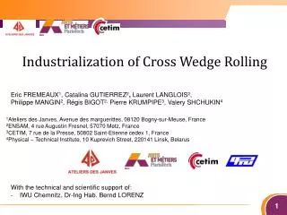
Industrialization of Cross Wedge Rolling. Eric FREMEAUX 1 , Catalina GUTIERREZ 2 , Laurent LANGLOIS 2 , Philippe MANGIN 2 , Régis BIGOT 2, Pierre KRUMPIPE 3 , Valery SHCHUKIN 4. 1 Ateliers des Janves , Avenue des marguerittes , 08120 Bogny-sur-Meuse, France

E N D
Industrialization of Cross Wedge Rolling Eric FREMEAUX1, Catalina GUTIERREZ2, Laurent LANGLOIS2, Philippe MANGIN2, Régis BIGOT2, Pierre KRUMPIPE3, Valery SHCHUKIN4 1Ateliers des Janves, Avenue des marguerittes, 08120 Bogny-sur-Meuse, France 2ENSAM, 4 rue Augustin Fresnel, 57070 Metz, France 3CETIM, 7 rue de la Presse, 50802 Saint-Etienne cedex 1, France 4Physical – Technical Institute, 10 Kuprevich Street, 220141 Linsk, Belarus • With the technical and scientific support of: • IWU Chemnitz, Dr-Ing Hab. Bernd LORENZ
Summary • Introduction • CWR principle • Advantages and disadvantages • Objectives • CWR tool design • Design rules • Application • To increase CWR Tool Life • Identification of the limiting phenomenon • Experimental – numerical investigation • Conclusion and future evolution
Introduction CWR is a metal forming process in which a cylindrical billet is plastically deformed into another axisymmetrical shape by the action of wedge segments. The two main configurations industrially developed are: (A) flat type and (B) two roll type [Li, et al., 2008]. Flat wedge type Two-roll type CWR Facilities at Ateliers Des Janves
Cross wedgerolling Rolled parts can be of simple diameter reduction or of several reductions. Simple diameter reduction. CWR tool with 1 wedge. [PATER 2010] Double-diameter reduction. CWR tool with 2 wedges. Five-diameter reductions CWR tool with 5 wedges
Advantages and disadvantages • Benefits [Li and Lovell 2002] [Li and Lovell 2008] • Material and energy saving process with lower environmental impact. • Higher productivity (cycle time up to 5 – 10 sec). • High accuracy and maximum proximity to required dimensions of finished products. Cross Wedge Rolling Forging Rolling • Difficulties [Weronski and Pater 1992]: • Process with a high degree of technological complexity • Number of parameters affecting the stability of the process. • Relationship between the parameters that must be correctly chosen in order to avoid failures. • Slight variations in basic parameters can have a high impact on the rolled part. • CWR tool design has been based on the experience and intuition of designers. No decision-making tools publicly available to the date. • Tool manufacturing and development cost
Introduction • Application • Preform: Hot forging of connectingrod • Robotizedforgingworkcell • Hammer • Productivity • 150% higher / Classical line • Quality: number of scrap parts / 2 • Materialsaving (5%-15%)
Objectives • In order to increase the performances of CWR • To reduce the developing time and cost of new CWR tool • To reduce the experimental part of the tool development • To automate as far as possible the tool design methodology • To improve the life of the CWR tools • To increase the life of CWR (Number of parts manufactured per tool) • To stabilize the tool behavior • To reduce the dispersionof the tool life • To reduce the number of defect types limiting the tool life
Summary • Introduction • CWR principle • Advantages and disadvantages • Objectives • CWR tool design • Design rules • Application • To increase CWR Tool Life • Identification of the limiting phenomenon • Experimental – numerical investigation • Conclusion and future evolution
CWR Tool Design • It is based on the parametric definition of the desired rolled part and on the parametric definition of the tool. Cc α 03 Profil 03 - Identification of the tool design parameter Le Diagram of a wedge configuration [PATER 2003] β 03 Ce Profil 02 Yp ϒ Cg α 02 α 01 β 01 Profil 01 β 02 Cp x z x y y z Parameters of die configuration Geometrical parameters of die configuration
Cross wedgerollingtool design procedure COLT • Integrate the state of art and expertise as far as possible • Design rules found in literature and identified during experimental work. • Design rules are associated with stability index • Flexible tool by allowing updating of the already existing rules and the implementation of new design rules; Design rules [Fu and Dean 1992] Risk of central porosity [Fu and Dean 1992] Necking • Stability Index: • Associatedwith design parameters • or function of design parameters • Associatedwitheachdefect
Cross wedgerollingtool design procedure COLT • Output: • Geometrical parameters of the CWR tool • Coordinates of remarkable points for • flat type and/or • two-roll type • Stability Indexes (potential defects) .txt file with coordinates of remarkable points
Cross wedgerollingtool design procedure COLT Conclusions • A decision supporting methodology for the designing of the tool in CWR is being developed. • Solution provided by COLT is not expected to be immediately efficient but as close as possible to a performant solution. • Synthesis of literature and experimental rules. • The designing rules allow the selection of basic parameters. • An stability index is introduced to take into account the inconsistencies in literature. Benefits • The advantages of the methodologyare: • Non-expert user will have a first guided approach to the CWR process. • Identification of the potential defects with the associated basic parameters. • Flexibility of the methodology by the updating of exiting rules and implementation of new ones.
Summary • Introduction • CWR principle • Advantages and disadvantages • Objectives • CWR tool design • Design rules • Application • To increase CWR Tool Life • Identification of the limiting phenomenon • Experimental – numerical investigation • Conclusion and future evolution
CWR Tool Life • Tool Life in CWR are limited by geometrical defects of the rolled part • The forged part doesn’t meet its requirements • Defects • Dimension • The shape of the rolled part cannot be hot forged Spiral groove and striation Center cracking Common defects on CWR products [Li and Lovell 2002]
CWR Tool Life Methodology • Identification of the statistical correlations between: • Geometrical, kinematical, thermo mechanical parameters • and • Limiting phenomenon • Initial value and evolution of the parameters along the tool life • Relative initial position of the different parts constituting the tools • Differential Kinematics of the tools • Evolution of the shape of the tool due to wear • Distribution of the temperature at the surface of the tool • …
CWR Tool Life • Synchronism of two-roll tool during rolling Synchronism of the grooves passing through a fixed frame was studied. High speed camera Schema installation recorded image by the high speed camera An analysis of the average angular velocity was calculated by measuring the time between two grooves through the fixed frame.
CWR Tool Life • Evolution of tool wear Non-contact 3D measurement methods • Relative position of the different parts of the tool • Evolution of the geometry due to wear Computer stereo vision
CWR Tool Life • Conclusions and perspectives • 1- Experimental and statistical identification of the correlationbetween • tool and processparameters and the phenomenonlimitingtool life • 2- Experimental and modelling-simulation investigation • Statistical relation Qualitative – Quantitative Physical relation • 3- To design and to implement solutions in order to increase and better control • the life cycle of the CWR tool. • 4- Integration of the result as knowledgewithn the tool design methodology • New design rules • New processparameters
Industrial – AcademicPartnership • ENSAM – CETIM • State of the art • Identification of the key parameters • Initial version of the design methodology • (Formalization of the know-how) • Scientific et technological support of PTI and IWU • Financial support of Region Lorraine • Ateliers des Janves • Investment • Industrialimplementation of the CWR • Know-how and experience Industrialrequirement Know-how Industrialfacilities Skill - Knowledge management - Process thermo mechanicalsimulation - Measurement and control of manufacturing process • Fruitfull collaboration • Increase of the skillbased on scientific and technologicalapproach • Integration of the skill as computer aidtool for the industrialization of the process
Thankyou for your attention