LIBS Detector System Design & Preliminary Testing
160 likes | 181 Views
This document discusses the design and testing of a Laser-Induced Breakdown Spectroscopy (LIBS) detector system for species identification in wood. It covers tasks such as acquiring components, interfacing with a computer, designing the optical configuration, constructing a prototype, and field testing and evaluation. The document also includes analysis results and the field calibration of the detector system.

LIBS Detector System Design & Preliminary Testing
E N D
Presentation Transcript
LIBS Detector SystemDesign & Preliminary Testing David Hahn, Tom Moskal, Ken Iida Department of Mechanical Engineering University of Florida July 9, 2001
Laser-induced pl as ma Atomic emission lines provide species identification Emission collection Emission Intensity Fiber optic Detector 410 415 420 425 430 435 440 Wavelength (nm) Laser-Induced Breakdown Spectroscopy (LIBS) Sample Pulsed laser Spectrometer
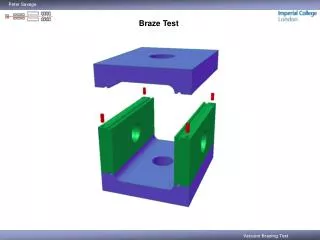
LIBS detector: Tasks and status • Acquire laser and spectrometer components • Interface spectrometer to the computer for data acquisition with external triggering • Optical configuration design and design of detector package • Construct prototype detector system • Synchronize spectrometer data acquisition with firing of laser
LIBS detector: Tasks and status (con’t) • Interface output trigger signal with PC for firing strobe light upon CCA detection • Design and build detector mount • Field test instrument (4-20-01) • Field testing and evaluation (current)
Detector configuration Laser To PC
Data acquisition Plasma emission Laptop computer Strobe trigger Fiber optic Spectrometer Data acquisition and analysis Ext. trigger from laser
Laser pulse (10 ns) Plasma emission (25 us) Chromium emission (10 us) Delay Detector Pre-trigger Instrument synchronization 0 Time
Identification of CCA-treated wood 14000 Calcium 12000 10000 8000 Emission Intensity Peak 6000 Base Chromium 4000 2000 0 410 415 420 425 430 435 440 Wavelength (nm)
Field calibration of detector system • Detect CCA-treated wood by presence of chromium atomic emission • Non-treated wood also emits light • (background emission) at the same spectral region • Select a threshold for CCA detection
Single laser shots: Untreated wood LIBS Cr Signal Laser Shot Number
Single laser shots: Treated wood LIBS Cr Signal Laser Shot Number
Single-shot analysis 95% accuracy 92% accuracy 10-shot average 99% accuracy 100% accuracy Analysis of single laser shots Untreated Lumber Treated Lumber Cr Signal
Output signal for detection of treated wood • Fire strobe lights when CCA is detected • Requires firing rate of 2 Hz and TTL trigger logic • NOVA Electronics built a custom strobe unit with four output channels
Sarasota field test on 7-3-01 Threshold
Summary of LIBS work to date • Successfully detect CCA-treated wood by presence of chromium in the field • Indicator strobe enables real-time, on-line sorting with accuracy approaching 100% • Continue to assess accuracy of LIBS-based detector and to formulate system improvements