Download
1 / 25
260 likes | 364 Views
This presentation by Peter McIntyre and Akhdiyor Sattarov from Texas A&M University discusses the optimization of quadrupole magnets for the International Linear Collider's (ILC) final focus system. It outlines crucial challenges such as maximizing gradient, proximity to the interaction point (IP), and heat/radiation damage tolerance. The design utilizes structured Nb3Sn cables and advanced fabrication techniques, including Finite Element Analysis (FEA) for stress analysis. The presentation addresses cooling strategies, insulation alternatives, and innovative magnet methodologies to enhance performance while mitigating risks from particle losses.

E N D
Optimizing Quadrupole Design for ILC Final Focus Peter McIntyre and Akhdiyor Sattarov Texas A&M University Presented to ILC BDS Working Group 7/19/2005.
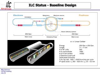
ILC Strawman BDS Layout e- e+ 2 mrad IR, L* = 3.5 m 20 mrad IR, L*= 3.5 m
Challenges • Maximize gradient • Move as close as possible to IP – no steel • Can Q0 be designed to tolerate heat, radiation damage from synchrotron radiation?
These are the same challenges that one faces in optimizing IR for LHC detector
Q1 is in harm’s way of particle lossesanalog effect for ILC is SR Q1 D1 Multiplicity ~ f() e-bt Eparticle ~ pt / So energy flow concentrates strongly down the beam direction.
Design Q1 using structured cable 3 mm 6-on-1 cabling of Nb3Sn strand around thin-wall inconel X750 spring tube Draw within a thicker inconel 718 jacket Interior is not impregnated – only region between cables in winding Volumetric cooling to handle volumetric heating from particle losses
Stress analysis of structured cable • Motivation, Design and Finite Element Analysis (FEA) of the 6-on-1 cable in conduit • Nb3Sn: Heat treatment, properties, peculiarities, and how to work with it • A few words about the conduit and Inconel X 750 • Fabrication of the cable and coil • Testing of coils and short samples • Conclusion
Cable design Six strands of Nb3Sn are cabled around a hollow Inconel X 750 tube Then the assembly is sheathed in an outer armor that is drawn onto the 6-on-1 configuration By virtue of its low effective Young’s modulus, the hollow inner tube protects the Nb3Sn wire from external loads
Mesh for FEA Apply 100 MPa external load, look at how it distributes in the cable elements.
Ironless Quadrupole for Q1 Impregnate rad-hard filler between cables, but leave interior of cables free for He flow 20 mm bore radius, 340 T/m 4.5-6 K supercritical cooling
No insulation between cables • During normal operation, current follows superconductor. • During quench, current redistributes as necessary, no voltage can develop, coil quenches as if it were a single turn. • Insulation is traditionally the weak link for radiation damage. • No insulation what is next weak link?
Magnetics methodology Remove turns in regions of Bmax to enhance gradient Placement of inner turns controls multipoles Place inner turns at smallest radius possible: G Bmax/R
Cryogenics • All turns have jackets opened at ends • Liquid helium flows through hollow channels in cables – superfluid or supercritical? • Zone flow in radial regions of similar Q • Probably can handle Q ~ 100 W/m cryogenic load kerf cuts around end arcs of each turn Voids between turns filled to seal He
Structured cable works nicely with BNL’s serpentine coil winding technique by Brett Parker: 50 mm bore radius, 145 T/m gradient
Fabrication of structured cable Prototype cabler used to make ~10 m piece lengths. Long lengths can be made at N.E. Electric.
Compressing Inconel sheath on cable Short lengths prepared by drawing sheath onto cable. For long lengths, compress sheath in hydraulic die. Best is to compress to rounded hex final shape.
Bending cable on tight radius does not damage strands Bending cable ovals outer sheath, ovals inner tube, but leaves the 6 strands round. 0.8 mm strand, 1 cm radius OK. Important for small-bore quad!
Other special magnets for LHC IR-any use to ILC? • block-coil Nb3Sn quads to 450 T/m • Levitated pole dipole – 8 T bend, ~impervious to swept losses
Q2, Q3: push gradient usingblock-coil Nb3Sn quadrupoles 450 T/m @2 K superfluid cooling (w/iron)
D1: levitated-pole dipole 8.0 T 4.5 K Cold iron pole piece, warm iron flux return. Cancel Lorentz forces on coils, pole steel.
This is what optimized superconducting magnets can do for LHC IR Comparison to baseline IR: Reduce * 0.15 m Reduce* 5 km Reduce # of subsidiary bunch crossings 5 Reduce sensitivity to error fields and placements Open space for another doublet to fully separate corrections in x, y.
Help me to optimize quads for ILC IRs • Micro-lattice, what apertures are critical? • What is flux distribution in synchrotron light, spent beam in first quad region? • How close into detector can an ironless quad be placed? • Remember: for most optical effects of multipoles, misalignments, etc., the closer Q0 is to the IP the less the impact on luminosity.