ILC Design Overview
ILC Design Overview. Nick Walker (DESY/GDE) GDE Internal Cost Review FNAL 13.11.12. Contents. Requirements (from Physics and Detector) Design evolution to the TDR baseline Baseline 500 GeV E cm Parameters Approach to Site-Dependent D esign Variants ILC overview (intro to detail talks)

ILC Design Overview
E N D
Presentation Transcript
ILC Design Overview Nick Walker (DESY/GDE) GDE Internal Cost ReviewFNAL 13.11.12 N. Walker ILC PAC TDR review
Contents • Requirements (from Physics and Detector) • Design evolution to the TDR baseline • Baseline 500 GeV Ecm Parameters • Approach to Site-Dependent Design Variants • ILC overview (intro to detail talks) • RTML and bunch compressor • Emittance preservation (beam dynamics) • Low Ecm Running • Luminosity upgrade • TeV energy upgrade N. Walker ILC PAC TDR review
Requirements from ‘the customers’ http://ilc-edmsdirect.desy.de/ilc-edmsdirect/document.jsp?edmsid=*948205 • Baseline: • Energy range: 200 ≤ Ecm ≤ 500 GeV • ∫Ldt ~ 500 fb-1 (in four years) • Ability to make energy scans(about Ecm) • DE/E ≤ 0.1% • both pulse ‘jitter’ and bunch/train energy spread • Electron polarisation ≥ 80% • Support for two detectors • push-pull • Calibration at Z-pole (~90 GeV) • but low lumi. • Beamstrahlung ‘low’ (~few %) • Upgrades: • Energy upgrade to ~ 1 TeV important • Not to exclude e-e-or gg collider options • Polarised positrons ≥50% • Giga-Z (Z factory with several 1033 cm-2s-1) focus of GDE design efforts conceptual approach considered. acknowledged but not considered in any detail N. Walker ILC PAC TDR review
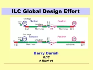
ILC in a Nutshell Polarised electron source Damping Rings Ring to Main Linac (RTML) (inc. bunch compressors) e+ Main Linac Beam Delivery System (BDS) & physics detectors Beam dump Polarised positronsource e- Main Linac not too scale N. Walker ILC PAC TDR review
Design Evolution: RDRTDR • 2007 Reference Design Report and cost estimate • 2008-2012 Technical Design Phase • Re-evaluation of baseline layout updated design • Updated value estimate RDR SB2009 N. Walker ILC PAC TDR review
Scope of Design Changes • 31.5 MV/m average accelerating gradient including ±20% spread • Single tunnel for Main Linacs • Undulator-based e+ source relocation to end of e- Main Linac • RDR: located at nominal 150 GeV point in elec. main linac • Reduced beam-power parameter set • 2625 1312 bunches per pulse (8.8 5.8mA) • reduced klystron / modulator count (~30%) • and… • 6.43.2km circumference Damping Ring • Central region integration (general) • RTML, sources and BDS integration N. Walker ILC PAC TDR review
ILC Published Parameters Luminosity Upgrade Centre-of-mass independent: Advantage of SCRF technology: long pulses http://ilc-edmsdirect.desy.de/ilc-edmsdirect/item.jsp?edmsid=D00000000925325 N. Walker ILC PAC TDR review
ILC Published Parameters Centre-of-mass dependent: http://ilc-edmsdirect.desy.de/ilc-edmsdirect/item.jsp?edmsid=D00000000925325 N. Walker ILC PAC TDR review
ILC Published Parameters Focus of design (and cost!) effort Centre-of-mass dependent: http://ilc-edmsdirect.desy.de/ilc-edmsdirect/item.jsp?edmsid=D00000000925325 N. Walker ILC PAC TDR review
ILC Footprint There are the SCRF main linacs…. … and there is everything else. N. Walker ILC PAC TDR review
Site-Dependent Designs • Top-level parameters • Accelerator layout • lattice • geometry • parameters • etc. • CFS requirements • Central region (source, BDS, DR) • RTML (bunch compressors) • Civil engineering solutions • topography • geology • Main linac layout • RF power distribution ( CFS) cost effective tunnelling methods
SCRF Linac Technology * site dependent Approximately 20 years of R&D worldwide Mature technology Presentation by A. Yamamoto N. Walker ILC PAC TDR review
RF Power Source Marx modulator 10MW MB Klystron Adjustable local power distribution system Presentation by S. Fukuda N. Walker ILC PAC TDR review
Main Linac Parameters (500 GeV) * at 31.5 MV/m N. Walker ILC PAC TDR review
Site Dependence I: KCS KlystronCluster Scheme Novel system 35×10 MW MBK 350 MW Feeds ~1 km of linac via over-moded circular WG (∅ 48 cm) ~8 MW ‘tapped-off’ every 26 cavities Special CoxaxialTap-Offs (CTO) used for both combining and splitting N. Walker ILC PAC TDR review
Site Dependence I: KCS “Flat” topography site-dependent design Presentations by M. Ross and V. Kuchler N. Walker ILC PAC TDR review
Site Dependence II: DKS “Komoboko” tunnel Reduced surface presence. Horizontal access Most infrastructure underground. “Mountainous” Topography site-dependent design Presentation by A. Enomoto N. Walker ILC PAC TDR review
Site Dependence II: DKS Distributed Klystron Scheme accelerator cryomodules presentations by M. Ross and S. Fukuda N. Walker ILC PAC TDR review
ILC in a Nutshell Polarised electron source Damping Rings Ring to Main Linac (RTML) (inc. bunch compressors) e+ Main Linac Beam Delivery System (BDS) & physics detectors Beam dump Polarised positronsource e- Main Linac not too scale N. Walker ILC PAC TDR review
Ring To Main Linac (RTML) (FoDo lattice) 5 GeV 5 GeV 15 GeV 15 GeV 5 GeV 5 GeV R56 = -372 mm R56 = -55 mm ÷3 ÷6.7 bunch length: 6 mm 0.9 mm 0.3 mm beam energy: 5 GeV 4.8 GeV 15 GeV DE/E: 0.11% 1.42% 1.12% DKS also used for flat topography site N. Walker ILC PAC TDR review
RTML / Bunch Compressor • Emittance preservation primary challenge • fast ion instability in ~30km long return line • stray time-varying fields (≤2 nT). • spin rotation (solenoids x-y coupling) • RF and long bunch / large DE/E • wakefields, coupler kicks, cavity tilt effects… • beam based alignment • Tight requirements on phase/amplitude stability • timing at IP luminosity loss • 0.24° / 0.48° stability (correlated/uncorrelated) • LLRF challenge N. Walker ILC PAC TDR review
Central Region • 5.6 km region around IR • Systems: • electron source • positron source • beam delivery system • RTML (return line) • IR (detector hall) • damping rings • Complex and crowded area Central Region common tunnel N. Walker ILC PAC TDR review
Central Region Example: Flat Topography The central region beam tunnel remains a complex region. Complete, detailed and integrated lattices are now available service tunnel Generic design used for geometry and generating component counts and CFS requirements. CFS (particularly CE) solutions are site-dependent! N. Walker ILC PAC TDR review
Damping Rings Values in () are for 10-Hz mode Many similarities to modern 3rd-generation light sources presentation by G. Dugan N. Walker ILC PAC TDR review
Positron Source (central region) • located at exit of electron Main Linac • 147m SC helical undulator • driven by primary electron beam (150-250 GeV) • produces ~30 MeV photons • converted in thin target into e+e- pairs yield = 1.5 not to scale! Presentation by W. Gai N. Walker ILC PAC TDR review
Polarised Electron Source • Laser-driven photo cathode (GaAs) • DC gun • Integrated into common tunnel with positron BDS Presentation by W. Gai N. Walker ILC PAC TDR review
BDS and MDI Geometry ready for TeV upgrade e+ source e- BDS electron Beam Delivery System Presentation by K. Buesser N. Walker ILC PAC TDR review
IR region (Final Doublet) • FD arrangement for push pull • different L* • ILD 4.5m, SiD 3.5m • Short FD for low Ecm • Reduced bx* • increased collimation depth • “universal” FD • avoid the need to exchange FD • conceptual - requires study • Many integration issues remain • requires engineering studies beyond TDR • No apparent show stoppers BNL prototype of self shielded quad Presentation by K. Buesser N. Walker ILC PAC TDR review
MDI (Detector Hall) Flat-topography detector hall concept Presentation by K. Buesser N. Walker ILC PAC TDR review
MDI (Detector Hall) Mountainous-topography detector hall concept Presentation by K. Buesser N. Walker ILC PAC TDR review
Central Region Integration Damping Rings detector e+ main beam dump RTML return line e- BDS muon shield e+ source e- BDS 3D CAD has been used to developed beamline layouts and tunnel requirements. Complete model of ILC available. N. Walker ILC PAC TDR review
Where are we? • Requirements (from Physics and Detector) • Design evolution to the TDR baseline • Baseline 500 GeV Ecm Parameters • Approach to Site-Dependent Design Variants • ILC overview (intro to detail talks) • RTML and bunch compressor • Emittance preservation (beam dynamics) • Low Ecm Running • Luminosity upgrade • TeV energy upgrade N. Walker ILC PAC TDR review
Emittance Preservation • Damping Ring: gey = 20nm • ~30km RTML return line • Turn around and spin rotation • Bunch compressor (two-stages) • Acceleration (10km main linac) • Positron production (e- only) • Beam delivery system (non-linear optics) • Final Doublet and collision! • Budget 15 nm gey = 35 nm at IP N. Walker ILC PAC TDR review
Emittance Budgets Results of extensive simulations (over 10 years) Standard alignment (survey) errors assumed Several beam-based alignment techniques studied (most notably DFS) ‘Realistic’ simulation (including wakefields, non-linear fields etc.) Tuning algorithms (dispersive closed bumps, final focus tuning etc.) Dynamic errors included (ground motion, vibration, beam-based feedback etc.) 35nm @ IP looks OK on average (in simulation!) N. Walker ILC PAC TDR review
Low Ecm Running (<300 GeV) • Positron production (yield) drops with <150 GeV • Low Ecm running (≤250 GeV) 10Hz mode • Alternate pulses for e+ production: • 150 GeV e- pulse to generate positrons • Ecm/2 e- pulse for luminosity • Ramifications: • 100ms store time in DR shorter damping times • Need to dump 150 GeV production pulse after undulator (new beamline, pulsed-magnet system) • Pulsed trajectory-correction system before undulator for 150 GeV production beam. • Electron Main Linac requires no modification • Installed AC power sufficient for ~½ energy operation at 10Hz. N. Walker ILC PAC TDR review
Luminosity Upgrade • Concept: increase nb from 1312 → 2625 • Reduce linac bunch spacing 554 ns → 336 ns • Increase pulse current 5.8 → 8.8 mA • Increase number of klystrons by ~50% • Doubles beam power ×2 L (3.6×1034cm-2s-1) • Damping ring: • Electron ring doubles current (389mA 778mA) • Positron ring: possible 2nd (stacked) ring (e-cloud limit) • AC power: 161 MW 204 MW (est.) • AC power increased by ×1.5 • shorter fill time and longer beam pulse results in higher RF-beam efficiency (44% 61%) N. Walker ILC PAC TDR review
Luminosity Upgrade Adding klystrons (and modulators) KCS Building MountainTopography (DKS) Flat Topography (KCS) Damping Ring: N. Walker ILC PAC TDR review
TeV Upgrade <26 km ? (site length <52 km ?) 1.1 km 2.2 km 10.8 km <10.8 km ? 1.3 km Main Linac BDS e+ src IP bunch comp. Assume Higher Gradient Main Linac <Gcavity> = 31.5 MV/m Geff ≈ 22.7 MV/m (fill fact. = 0.72) central region Snowmass 2005 baseline recommendation for TeV upgrade: Gcavity = 36 MV/m ⇒ 9.6 km (VT ≥ 40 MV/m) Based on use of low-loss or re-entrant cavity shapes N. Walker ILC PAC TDR review
TeV upgrade: Construction Scenario 500GeV operations start civil construction Main Linac BDS BC e+ src IP civil construction + installation 500GeV operations BC Main Linac BDS e+ src IP Installation/upgrade shutdown BC Main Linac BDS e+ src IP final installation/connection removal/relocation of BC Removal of turnaround etc. Installation of addition magnets etc. Commissioning / operation at 1TeV BC Main Linac BDS e+ src N. Walker ILC PAC TDR review IP
TeV Parameters (2 sets) PAC constrained ≤300 MW shorter bunch length(within BC range) horizontal focusing main difference low and high beamstrahlung N. Walker ILC PAC TDR review
Detailed Presentations N. Walker ILC PAC TDR review