Final Focus Design
Final Focus Design. Pantaleo Raimondi and Andrei Seryi SLAC Oct-5, 2000. Plan of the talk. Final Focus history Basic concepts of a “traditional” Final Focus Problems of a “traditional” approach Concepts of a new Final Focus Comparison of traditional and new FF

Final Focus Design
E N D
Presentation Transcript
Final Focus Design Pantaleo Raimondi and Andrei Seryi SLAC Oct-5, 2000
Plan of the talk • Final Focus history • Basic concepts of a “traditional” Final Focus • Problems of a “traditional” approach • Concepts of a new Final Focus • Comparison of traditional and new FF • Scaling to multi TeV region for the new FF • Linear Collider Test Facility • Conclusions
Final Focus task FF should focus the beams to small sizes at IP • Chromaticity of FF is determined by the final doublet. • FD chromaticity scales as L*/b*, and thus the chromatic dilution of the beam size Ds/s ~ sE L*/b* is very large. • Design of a FF is driven by the necessity of compensating the FD chromaticity.
Concepts of a “traditional” Final Focus • Chromaticity is compensated in dedicated sections. • Geometrical aberrations are canceled by using sextupoles in pairs with M= -I. CCX CCY FFTB and extrapolated NLC-FF design conceptually identical but...FFTB ~150m long! NLCFF ~1750m long! Optics of the traditional NLC FF. L* = 2m, bx* =10mm and by* =0.12mm.
SLC Final Focus had X & Y Interleaved Chromatic Correction Sections, to save in total length Bends Short to save in total length Background issues hardly consideredResulting aberrations small for the design beam parameters, but the limiting factors for the achieved ones: - Less Current- Smaller Emittances Beta-Match Y CCS Y FT SLC Final Focus S[ft] Beta-Match X CCS X FT S[ft]
Extensive tracking identified large contribution to the background from high order aberrations in the “FD phase” generated in the CCS.As an example of the better understanding, sextupoles were added to minimize SLC Background Luminosity greatly improved, since smaller IP ’s were allowed and detector Up-Time increased
FFTB Final Focus SLC-FF and SLC-FF achievements SLC Final Focus X & Y spot sizes limited by background and aberrations Jitter and background were some of the FFTB limitation * Most of the issues on tuning and understanding the FFS’s optic solved through the years of SLC and FFTB operations
Problems of traditional FF • Chromaticity is not locally compensated • Bandwidth is limited since M = -I for off energy particles. • High sensitivity to dE in between the sources of chromaticity (due to wake-fields, synch.radiation). • Bends have to be long and weak. • Off-energy particles at IP and FD phases mix. • Collimation in both FD and IP phases is necessary. • System very long and scaling to higher energies is difficult. /
“Ideal” FF requirements • Chromaticity corrected locally. • Number of bends minimized. • Dynamic aperture (preservation of the linear optics) as large as possible. • System as simple as possible. • System optimized for flat beams.
Principles of the “ideal” FF • A Final Doublet is required to provide the necessary demagnification. • The chromaticity is cancelled locally by two sextupoles interleaved with the FD together with a bend upstream to generate dispersion across them. • Geometric aberrations of the FD sextupoles are cancelled by two more sextupoles placed in phase with them and upstream of the bend. • Four more quadrupoles are needed for -matching
Chromatic correction in FD • Straightforward in Y plane • a bit tricky in X plane: sextup. quad x + h d IP If we require KSh = KF to cancel FD chromaticity, then half of the second order dispersion remains. Solution: The -matching section produces as much X chromaticity as the FD, so the X sextupoles run twice stronger and cancel the second order dispersion as well. KS KF Quad: Second order dispersion chromaticity Sextupole:
Second and higher order aberrations • Second order aberrations produced by sextupoles are cancelled if where all nonzero parameters are arbitrary This requirements is less stringent than M=-I , so additional degrees of freedom available for fine tuning of higher order aberrations. • Higher order aberrations can be made to vanish for our beam parameters.
Third order aberrations • Third order geometric aberrations generated by sextupoles: where y12 and y34 are elements of transfer matrix between SF1 and SD1 • U1222 and U3444 typically negligibles • U1244 and U3224 can be made to vanish
Traditional and new FF A new FF with the same performance as NLC FF can be ~300m long, i.e. 6 times shorter Traditional NLC FF, L* =2m New NLC FF, L* =2m new FF
Extension of the “minimal optics” concept • New FF has potentially much better performance than the traditional FF • To use these capabilities and improve the system even further we incorporate: • Twice L* • allows the use of large bore superconducting quadrupoles • simplifies the design of the detector • One additional weak bend at the entrance enlarges bandwidth • One additional X-sextupole reduces horizontal aberrations • A decapole close to the first sextupole reduces 4th order chromatic aberrations • Soft bend downstream of the main bend reduces background
Optics of the new FF New FF with twice L* and with an additional bend and with soft bend. Larger L* allows the use of large bore quadrupoles which decreases collimation requirements. Larger L* also simplifies the design of the detector, and allows to make more rigid support of the FD. Optics of the new NLC FF. L* =4.3m.
Chromaticity in traditional and new FF Large chromaticity through the FF results in high sensitivity to dE along the way for the traditional system Traditional FFS, L* = 2m New FFS, L* = 4.3m Chromaticity is much smaller through the new FF.
IP bandwidth New NLC FF, version ff00 L* =4.3m Traditional NLC FF L* =2m IP bandwidth of the traditional and new NLC FF. (b/b0)1/2 -- the beam size defined from beta function vs DE/E s/s0 -- luminosity equivalent beam size vs DE/E L/L0 -- luminosity versus rms sE • The IP bandwidth is very similar for these systems.
FD bandwidth • The FD bandwidth is rarely discussed but very important • Large FD bandwidth is necessary to minimize background due to off energy particles • New FF has much larger FD bandwidth FD bandwidth of the Traditional and New NLC FF. Normalized betatron functions at the final doublet versus energy offset DE/E.
Collimation and background • Traditional FF does not preserve betatron phase of halo particles • New FF dos not mix IP and FD phase particles Beam at FD Traditional FF Incoming beam halo New FF Halo beam at the FD entrance. Incoming beam has 100 times larger coordinates in IP phase than in FD phase. Particles of incoming beam are placed on a surface of an ellipsoid with dimensions Ns (x,x',y,y',E) = (800,8,4000,40,20) times larger than nominal beam parameters. => Both IP and FD phase collimation required for traditional FF => Collimation design may benefit from the phase conservation feature of the new FF
Tuning and tolerances • Tuning is very similar for the new and traditional FF • by moving sextupoles the IP dispersion, waist, coupling can be adjusted • Positions tolerances are very similar Global measure of the FF tolerances: rms beam offset at the IP comes from vibration of optical elements produced by fast ground motion
IP beam offsets sensitivity to quad motion NLC-FF: IP OFFSET FOR A GIVEN QUAD OFFSET BLACK BARS: X WHITE BARS: Y NEW-FF: IP OFFSET FOR A GIVEN QUAD OFFSET BLACK BARS: X WHITE BARS: Y
Scaling with emittance • Increasing e will increase contribution of aberrations to s* • To keep the contribution of aberrations constant, the bend field must scale as B0 ~ e1/2 • This scaling is natural since h’/q* is then also constant Luminosity vs emittance for the new FF for the nominal, twice larger and twice lower field in the bends. Tracking without synchrotron radiation.
Energy range A fixed length FF can operate in a a wide range of energies. • Scaling to lower energies is easy. Rescaling of bends may be required. • SR contribution increase for high energies, but this growth is slowed by B0 ~ e1/2 ~ 1/g1/2 bend rescaling. Luminosity vs emittance for different bend field and beam energy New FF, ver.ff00. Tracking with sync.rad.
Scaling with energy • Length of traditional FF scales faster than linear with energy • For a 5 TeV CM, the length of traditional FF would be comparable to the length of the linac. • With the new FF scheme, a 5 TeV CM FF could be only about 700m.New FF Length 7/10
5.0 Tev/CM FF A FF for 3 - 5TeV CM collider can be just about 500 m long! Luminosity L/L0 versus beam energy. Beta functions at IP fixed. Angular dispersion at IP reoptimized at each energy .
New FF benefits • New FF is much shorter, providing a significant cost reduction for the collider. • New FF has similar bandwidth and several orders of magnitudes larger dynamic aperture than the traditional FF. • Background is an issue in the new design. Thanks to the expected benefits the collimation section may be relaxed with the new FF. • L* = 4.3m for the new FF simplifies engineering of the IP area, and probably helps the stabilization of the final doublet. • Scaling to multi-TeV region is extremely attractive for the new FF. • Further improvements of the system are under study… (and seem possible)
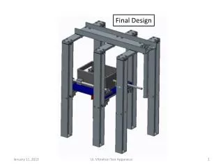
LCTF hypotesis It is conceivable to utilize the existing hardware at SLAC to realize a “Linear Collider Test Facility” • Test bench for various NLC applicable ideas and techniques • Logical and useful addition to NLCTA, Orion, ATF… • LCTF is an Interaction Region oriented test facility • Keep LCTF running until NLC is commissioned to maintain “beam handling state of the art” and train new people • LCTF can start with: • Test the New Final Focus scheme • Collide beams with NLC beta functions and bunch length, and ~ 70 nm vertical spot sizes • Develop and test IR vibration counteraction in vivo • Feed forward jitter suppression • Nano-meter level beam stabilization at the IP • …and much more
Basic Premises • e+ and e- beams are almost always available at the end of the Linac @ 30Hz and N~2.5e10, with good emittances • LCTF operation should not be in conflict with PEP-II operation • Refurbishing of Arcs and FF existing hardware reasonably affordable • The FF modifications, which mainly require a new FD, is affordable even by SLAC alone, but • LCTF will attract other labs and a solid international collaboration between all the labs involved in linear collider R&D could be established, to share efforts and costs.
Upgrades list • Damping Rings UpgradeRearrange the QFs and power feeds and add Booster Power Supplies. We expect to decrease both horizontal and equilibrium vertical emittances by about a factor 3:gx=1e-5m*rad gy=0.05e-5m*rad • Rings to Linac UpgradeA more suitable bunch compressor with better compression and less emittance growth should be studied and implemented. • Final Focus UpgradeThe Final Focus should be modified according to the new Final Focus scheme. We expect to have very small residual spot size dilutions down to NLC-like IP beta functions. Desired
LCTF parameters • Based on conservative extension of the achieved SLC parameters • Work at 30GeV@10Hz to reduce synch.rad in arcs, FF, and to reduce electricity bill (e.g. for arcs: ~ 1MW @45.6GeV per arc) • Work with lower current to improve beam stability • Beam Energy: 30 GeV • DR emittances: gx,y=1.0/0.05E-5m • FF emittances: gx,y=1.6/0.16E-5m • IP Betas: x=2mm y=0.2mm • Bunch length: z=0.8 - 0.2mm • IP spot sizes: x,y=750/75nm • Beam currents: N= 1.0e10 Emittances routinely achieved at SLC @45.6GeV and N= 1.5e10 : • Damping ring: gx,y=2.9/0.15E-5m • Final focus: gx,y=4.0/0.30E-5m (synch.rad. Arc contribution: Dgx,y=1.1/0.15E-5m) LCTF parameters
LCTF Final Focus optics • Use existing SLC FF • Make MIN modifications • Required modifications: • final doublet • make bend B2 longer (to reduce sync.rad. effect in horiz. beam size) New final doublet Very preliminary solution LCTF final focus with bx,y=2/0.2mm, L*=1.5m
LCTF Final Focus optics • Chromo-geometrical aberrations: • acceptable • Tracking: OK in Y (~70nm) • x1.6 in X due to sync.rad. in B2 at 30GeV (worse at 46GeV) • by making B2 longer this effect can be almost eliminated • further optimization of the optics is possible bx,y=versus energy offset
Final doublet • Final doublet options: • superconductive: modify existing SC triplet, or build from scratch • electromagnets • permanent magnet quads • The permanent magnet options is most reasonable, because • not as expensive as SC (FF Cryo plant gone…) • allows to test solutions relevant for NLC • Variety of options of FD stabilization • active vibration suppression with reference to ground and inertial frame • feedforward correction of magnetic center position by dipole coils • etc.
Bunch compression in Arcs P.Emma
LCTF vibration issues • Quad stability in the FF tunnels is OK or almost OK for LCTF • Can deliberately make situation worse and learn to correct Vibrations of 54Q10 quad on FN20 girder In LCTF FF the tolerance for this quad jitter is a fraction of that for the final quads.
LCTF vibration issues • Vibration stability in the SLD detector is not sufficient • Need to improve quad center stability by about 10 times • Feedforward counteraction methods should be developed • Learning how to do this is one of the major goals of LCTF Examples of data from SLD vibration studies • Frequencies unreachable for beam-based feedback: f > rep.rate/20 • Linear Collider with 30Hz rep.rate and s* ~ 70nm will give experience applicable to LC with 120Hz and s* ~ 3nm
What else can be tested @ LCTF? • Tests of fast feedforward • Tests of traveling focus (allows to play with by/sz) Position of focus is moving during collision [Balakin 91]
More topics to be studied • IP jitter from quad vibrations • Linac to IP beam jitter feed forward • Structures on movers (X-band?) for emittance optimization • Global Linac Orbit control and stabilization • IP pair production • New schemes of Background reduction (e.g.Octupoles) • New diagnostic (e.g. OTRs) • and much more (any idea is welcome) ...
Conclusion • Final Focus System is a crucial point in the linear collider designs • Thanks to years of experience on SLC-FF and FFTB, we have been able to focus what are its main limitations and problems, and design a “Next Generation FFS”. • The present scheme allows for a collider that could be “adiabatically” upgraded in energy through the years up to 5TeV/CM, if the physics community requires it. • More could be gained with moderate money investment. An “LCTF” International Collaboration could better focus all the efforts toward a unique and more optimal Beam Delivery System design.