Download
1 / 88
880 likes | 1k Views
Discover the principles of network routing through Traceroute and explore various transmission media and fiber optic cables. Learn about signal propagation, modulation, data transmission, and bit encoding methods.

E N D
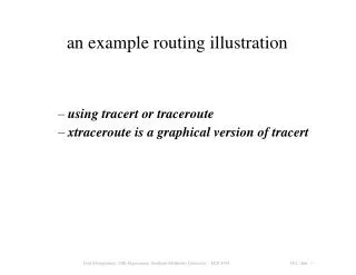
using tracert or traceroute xtraceroute is a graphical version of tracert an example routing illustration
layer 1: the physical layer • node: router or host • host: general purpose computer • router: general purpose or custom hardware • physical layer connection through network adaptor • network adaptor: NIC (network interface card)
topic 1: transmission media • guided (see next slide) • unguided • laser, radio satellites
guided physical media • magnetic media (e.g. tapes & disks) • twisted pair (e.g. UTP Cat 3, UTP Cat 5) • UTP = Unshielded Twisted Pair; Cat = Category • (Cat 5 has more twists per cm than Cat 3) • coaxial cable (e.g. cable TV) • thick • thin • optical fiber (e.g. submarine and backbone links) • single mode • multi mode • wireless (RF, microwave, infrared)
principles of fiber optics (a) light rays from inside a silica fiber impinging on the air/silica boundary at different angles (b) light trapped by total internal reflection
fiber optic cables (a) side view of a single fiber (b) end view of a sheath with three fibers
1. single-mode fiber (SMF): core ~8--12mic 2. multi-mode fiber (MMF): core ~50mic two types of fiber optic cables
wired media capacities cable typical b/w distances category 5 twisted pair 10 - 100 Mbps 100 m thin-net coax 10 - 100 Mbps 200 m thick-net coax 10 - 100 Mbps 500 m multimode fiber 100 Mbps 2 km single-mode fiber 100 - 10000 Mbps 40 km
common carrier bandwidths service bandwidth DS1 1.544 Mbps DS3 44.736 Mbps STS-1 51.840 Mbps STS-3 155.250 Mbps STS-12 622.080 Mbps STS-48 2.488320 Gbps STS-192 9.953280 Gbps
nature of signal in medium (air/glass/Cu):- electromagnetic (EM) waves speed of EM wave depends on medium example: speed of light in vacuum: 3 x 10⁸ meters/sec speed of electrical signals in copper: 2/3 x speed of light in vacuum signal characteristics & data rates
= c' / f where, = wavelength of signal c' = speed of light (EM wave) in given medium f = frequency of signal frequency – wavelength relationship
q1: what are common problems in signal propagation? ans: 1. signal attenuation - and, different frequencies are attenuated differently! 2. delay distortion - Fourier components travel at different speeds! 3. noise - thermal noise - impulse noise - crosstalk data transmission
q2: how do you transmit information (bits)? ans: by modulation - superimpose electrical signal (corresponding to bits) onto a carrier wave; then, transmit in the medium - modulation can be of several types (see next slide) data transmission
“the sampling theorem” Harry Nyquist, Claude Shannon, et alia “exact reconstruction of a continuous-time baseband signal from its samples is possible if the signal is bandlimited and the sampling frequency is greater than twice the signal bandwidth maximum data rate of a finite bandwidth noiseless channel information theory
DC signaling (i.e., baseband signaling): bits encoded & transmitted as square waves (see next slide) suitable for short links, low speeds AC signaling (by modulation of a carrier wave) bits first encoded as square waves (see next slide); then, use these waves to modulate carrier; finally, transmit modulated carrier suitable for long-haul links, higher speeds data transmission: signaling
modems: electrical representation of data bits (a) a binary signal (b) amplitude modulation (c) frequency modulation (d) phase modulation
assertion: we could use a 2 signal-level system to represent data i.e., logic 0 = +5v and logic 1 = 0v any foreseeable problems? yes 1. is 0v = logic 0, or is it an idle transmitter? 2. DC bias on line therefore, we need better encoding strategies data transmission: bit encoding
four types of encoding schemes: NRZ (Non-Return to Zero) NRZI (Non-Return to Zero Inverted) Manchester 4B/5B (used in conjunction with NRZI) data transmission: bit encoding
bit encoding (cont'd.): fig 2.10 (textbook) required clock rates?
bit encoding problems with NRZ? 1. “baseline wander” - shift in average (source or perceived) signal strength 2. clock recovery problem - sender-to-receiver synchronization is lost (see next slide) instead, why not send clock signal over separate wire?
how to extract bits from received signal • separate clock cable too expensive • so, how to recover clock from data signal? • clock recovery depends on lots of transitions • “string of ones” sync problem (NRZI) • “string of zeros” sync problem (Manchester)
bit encoding using 4B/5B:table 2.4 (textbook) 4-Bit Data Symbol 5-Bit Code 0000 11110 0001 01001 0010 10100 0011 10101 0100 01010 0101 01011 0110 01110 0111 01111 1000 10010 1001 10011 1010 10110 1011 10111 1100 11010 1101 11011 1110 11100 1111 11101 how to encode in 4B/5B ... 1. first encode data into 5-bit code using table shown to right. (5-bit code ensures that no more than 1 leading zero & no more than 2 trailing zeros) 2. then, encode 5-Bit code using NRZI
points to ponder ... • does 4B/5B solve clock-sync problem? • - long string of zeros? • - long string of ones? • what is baud rate? is it the same as bit rate? • baud rate of NRZI? • baud rate for Manchester encoding? • baud rate for 4B/5B? • efficiency of encoding for above schemes? • which encoding scheme is most efficient? • which one is least efficient?
the material in the following slides is not in your textbook, but has been included here for your study addendum to topic 1:some additional material on the physical layer
radio transmission (a) radio waves in the VLF, LF, and MF bands follow curvature of earth (b) in the HF band, they bounce off the ionosphere
communication satellites geostationary satellites medium-earth orbit satellites low-earth orbit satellites satellites versus fiber
communication satellites communication satellites and some of their properties
communication satellite basics • launched by rockets • satellites must maintain orbit stationarity • satellites follow Kepler's laws of planetary motion • ability to correct orbital drift • old age of satellite: orbital decay and death
low-earth orbit satellites -- Iridium (a) the Iridium satellites form six necklaces around the earth (b) 1628 moving cells cover the earth
Globalstar (a) relaying in space (b) relaying on the ground
“unguided” laser transmission convection currents can interfere with laser communication systems
public switched telephone system • structure of the telephone system • “POTS” • the politics of telephones • “PSTN”, “telco”, “telecom”, “Baby Bells” • governments own, operate, and/or regulate • the local loop: modems, ADSL and wireless • “last mile”, “first mile” • trunks and multiplexing • switching
structure of the telephone system (a) fully-interconnected network “complete graph”, “clique”, “mesh” (context sensitive) (b) centralized switch (c) two-level hierarchy squares: “mesh” (context sensitive)
major components of the PSTN • local loops • analog twisted pairs going to houses and businesses • trunks • digital fiber optics connecting the switching offices • switching offices • where calls are moved from one trunk to another
wireless local loops Architecture of an LMDS system.
DSL: Digital Subscriber Line local loop Bandwidth versus distance over category 3 UTP for DSL.
the politics of telephones LATAs, LECs, and IXCs Circles are LEC switching offices. Each hexagon belongs to the IXC whose number is on it.
FDM: Frequency Division Multiplexing (a) original bandwidths (b) bandwidths raised in frequency (b) multiplexed channel
WDM: Wavelength Division Multiplexing Wavelength division multiplexing. DWDM, CWDM, ...
TDM: Time Division Multiplexing T1 framing
sampling for transmission over TDM Delta modulation. delta modulation
TDM of multiple data (voice) streams Multiplexing T1 streams into higher carriers. U.S. system: Synchronous Optical NETwork (SONET)
TDM framing Two back-to-back SONET frames. two SONET frames in sequence
standard TDM line rates SONET and SDH multiplex rates.