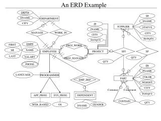
Control System Design: Motor, Valve & Tank Systems Analysis
This example covers the analysis and modeling of interconnected motor, valve, and tank systems for control design purposes. It includes block diagrams, equations, and system components like turbine generators.


Control System Design: Motor, Valve & Tank Systems Analysis
E N D
Presentation Transcript
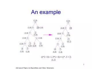
motor valve VR VL tank2 tank1 turbine generator 1.7 An example
VR K VM + K VM VR - VL VL Comparator vM=K(vR-vL) 1.7 An example
M vM TM Motor(armature controlled) Motor data: Armature winding resistance: Ra Armature winding inductance: La Motor constant: KM Back e.m.f. constant: Kb Rotor inertia: JM Shaft friction: BM 1.7 An example
Ra La ia + eb - T Jm Bm Armature controlled D.C. motor - revisited if=cnt. 1.7 An example
ia ea T + Km - eb Kb T Model: A block diagram 1.7 An example
For the problem at hand eb T vM TM M BUT Mechanical load on the shaft should be the total load Including that due to the valve also 1.7 An example
ia + Km - eb Kb Block diagram for the motor M TM VM • Where BM* & JM* show the total including the load 1.7 An example
M TM Valve Data q0=KvM Shaft friction: Bv q0 Shaft inertia negligible 1.7 An example
Kv M M q0 Valve model q0=KvM sM=M and BM*=BM+Bv , JM*=JM 1.7 An example
q0 A1 A2 h1 h2 R1 R2 q1 q2 p1 p2 p3 Double tank:Definitions p1=h1 p2=h2 1.7 An example
q0 h1 q0 h1 + - q1 q1 p1 Analysis Rate of change of heightXcross sectional area =added volume per unit time 1.7 An example
p1 p2 R1 q1 h1 q1 + - h2 1.7 An example
h2 q1 h2 + q1 q2 - p2 q2 1.7 An example
p2 p3 R2 q2 h2 q2 + - p3 1.7 An example
q0 h1 + q1 + h2 - - h2 + q1 - q2 Block diagram for the double tank system 1.7 An example
p3 q2 TG G 0 Turbine Turbine inertia & friction negligible A lossless (transformer-like) element 1.7 An example
iF TG G Generator Rotor inertia: JG vL Bearing friction: BG Field controlled type Field inductance: LF Field resistance: RF 1.7 An example
Rf Lf if + ef T Jm Bm Field controlled D.C. motor Fix armature current! ia=Cnt. Tm=Kmif 1.7 An example
if ef T Km Block diagram model 1.7 An example
Lf Rf + vL IL ia=Cnt. if Jm JG Jm Bm Bm BG G TG 1.7 An example
TG G N KG BG+sJG h2 iF vL N q2 iF=KGTG 1.7 An example
M q0 M h1 q1 VL VM - + ωG if ia TG + + + + VR K Kv N BG+sJG KG RF+sLF - - - h2 - q2 VL N comparator motor valve double tank turbine-generator 1.7 An example
End of Chapter Restart section Next chapter Restart chapter i The End General index End show 1.7 An example