Download
1 / 26
330 likes | 712 Views
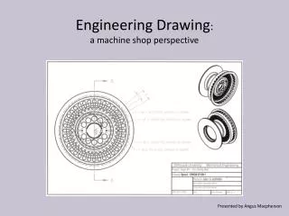
Engineering Drawing : a machine shop perspective. Presented by Angus Macpherson. What makes a good drawing?. It should clearly describe the part. The dimensions should match the intent of the part. Basic Information Included in a Drawing.

E N D
Engineering Drawing:a machine shop perspective Presented by Angus Macpherson
What makes a good drawing? • It should clearly describe the part. • The dimensions should match the intent of the part
Basic Information Included in a Drawing • Projected Views: show as many sides as required for completeness. • Cross Sections: the preferred way to show internal features. • Title Block: should include part name/number, type of material, number of parts required and the name of the designer.
Do not use default settings blindly. If the function requires different units or more or less precision adjust accordingly. Producing drawings requires time and thought. Whipping out a complex drawing in 15 minutes is not something to brag about. Drawings produced by more than one person should be consistent as to units and style. Use either metric or inch units, not both.
Very often the outside shape merely supports the features and is dimensionally irrelevant. Precise dimensions should only be applied where required, i.e. to features ( hole patterns, slots, shoulders etc.)
Basic Dimensions Always include the overall length, width and height
Where possible use standard sizes • Materials such as flat bar, round bar and shafting, sheet, plate, pipe, tube and structural shapes are all supplied in inch dimensions. • Fasteners (screws, bolts and nuts etc.) and bearings are supplied in both systems. • Milling cutters are usually inch sizes.
For clarity, spread details and dimensions over multiple sheets. However, the relationship between the sheets should be clearly indicated. All dimensions relevant to a particular detail should be contained on the sheet.
How you draw it, can greatly effect how much time is required to make it. The same bearing block through bored with retaining rings. Much simpler and quicker to machine Typical bearing block Difficult to machine, many operations
Holes are always dimensioned by Diameter Fillets and arcs are always dimensioned by Radius Arc Fillet Hole
Unless otherwise specified, holes are assumed to be plain and through the part You get what you ask for. ½ nc - 4 holes typ. .532 - 4 holes typ. .50 – 4 holes typ.
General tolerances are applied by machinist where specific tolerances are absent on a drawing Inches: X.XX ± 0.01 X.XXX ± 0.001 X.XXXX ± 0.0001 Metric: X.X ± 0.1 X.XX ± 0.01
Tolerances There are two types of tolerances: Dimensional and Geometric Position
Parts that are left and right handed should be placed on separate sheets
Just because you can draw it, does not mean it can be built. If there is any doubt, ask!
What is wrong with this drawing? The part is lost in the dimensions
What is wrong with this drawing? • The part is too small on the page. • Dimensions are crowded and confusing.
What is wrong with this drawing? Outside diameter is missing
Conclusion • Before starting the drawing consider if there is a simpler way to make the part. • If you are not sure, check with the person who will possibly have to make the part. • Use standard shapes and sizes wherever possible. • The drawing should clearly describe what is required. • The drawing should be large enough to be easily understood
If necessary draw the part on multiple sheets. • Left hand and right hand parts should be on separate sheets. • Dimensions should match the intent of the part. • Choose the units, either metric or inches, not both. • Avoid hard conversions.
Start by dimensioning the overall dimensions, then dimension the features. • Avoid chain dimensions wherever possible. • Use decimals sparingly, the more digits after the point the longer it will take to manufacture the part. • Only call for precision where it is required.
Holes should be dimensioned with diameter. • The way you dimension a hole determines the kind of hole you get. • Where more than one person is making the drawings, ensure that all the drawings are consistent in units and sequencing.
Before submitting drawings to your report, ask yourself the following: • Does the drawing clearly show what I want unambiguously. • Are all the dimensions there. • Have I indicated the material. • Have I indicated how many parts I need. • Have I indicated which holes are threaded and which holes are plain. • Have I discussed any of this with the techs.