Understanding Logic Families: Key Specifications and Parameters
470 likes | 740 Views
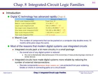
This document explains the crucial specifications of logic families, including speed of operation, power dissipation, figure of merit, fan-out, current and voltage parameters, noise immunity, operating temperatures, and power supply requirements. It emphasizes the importance of propagation delay time, power dissipation metrics, the range of acceptable operating temperatures, and flexibility in choosing different logic functions. The characteristics and classifications of bipolar and unipolar logic families are also examined, providing insight into their practical applications in electronic circuits.

Understanding Logic Families: Key Specifications and Parameters
E N D
Presentation Transcript
Unit 2 Logic Families
Important Specifications of Logic families • Speed of Operation • Power dissipation • Figure of Merit • Fan out • Current & Voltage Parameters • Noise Immunity • Operating temperatures • Power Supply Requirements • Flexibilities Available
Speed of Operation • Is specified in terms of propagation delay time • The delay time is measured between 50 % voltage levels at input & output as shown • The propagation delay is average of t PHL & t PLH i/o voltage waveform o/p voltage waveform tPHL tPLH time
TRANSISTOR NOT GATE CIRCUIT + Vcc Rc=2k Rb= 5k + Vo - + Vi - + Vc - Vbe
2. Power dissipation Power Dissipation is the amount of power dissipated in the circuit and is given by Pd = Vcc X Icc where Icc - average of Icc(0) & Icc (1) Vcc - Supply voltage Power dissipation is specified in milli volts . Low value is desirable 3. Figure of Merit It is defined as the product of Speed & Power dissipation Figure of merit (pJ) = Propagation delay ( ns) X Power dissipation (mw) It's also called as Speed Power Product . Low value is desirable 4. Fan out It is defined as Number of similar gates that can be driven by a gate High value is desirable as it reduces need for additional driver circuit
5.Current & Voltage Parameters Four Voltage Parameters VIH - High Level input Voltage - It's the minimum input voltage that is recognized by gate as a Logic 1 VIL - Low Level input Voltage - It's the maximum input voltage that is recognized by gate as a Logic 0 VOH - High Level output Voltage - It's the minimum output voltage that is available at the output of a gate as a Logic 1 VOL - LowLevel output Voltage - It's the maximum output voltage that is available at the output of a gate as a Logic 0 VOH VIH VIL VOL ∆ 1 = VOH - VIH ∆ 0 = VIL - VOL
5.Current & Voltage Parameters Six Current Parameters IIH - High Level input Current - minimum current that must be supplied by a driving source corresponding to Logic 1 voltage IIL - Low Level input Current - minimum current that must be supplied by a driving source corresponding to Logic 0 voltage IOH - High Level output Current - maximum current a gate can sink in Logic Level 1 IOL - Low Level out put Current - maximum current a gate can sink in Logic Level 1 Icc(1) - High Level supply Current - Supply current of a gate when it output = Logic 1 Icc(0) - Low Level supply Current-Supply current of a gate when it output = Logic 0 IIH IOH IIL IOL
6. Noise Immunity The Output & Input voltages of a gate are defined in earlier slide 1 state DC Noise Margin = 0 State DC Noise Margin = The Circuit's ability to tolerate Noise is referred to as Noise Immunity AC Noise Margin - VOH VIH VIL VOL ∆ 1 = VOH - VIH ∆ 1 = VOH - VIH ∆ 0 = VIL - VOL ∆ 0 = VIL - VOL 0 Volt Generally Noise is thought of as ac signal with amplitude & pulse width A Logic circuit can effectively tolerate a Large Noise amplitude if it is of very short Duration. (as compared to Gate's propagation delay) This is referred to as AC Noise Margin & is substantially greater than DC Noise Margin 7. Operating temperatures Accepted Temp Range : 00 C to +700 C for Consumer Eg. - ICs - 74XX Series : -550 C to +1250 C for Military purposes - 54XX series
8. Power Supply Requirements • Low power requirement - preferred for Battery Operated Equipments • 9. Flexibilities Available • Flexibility available with a Logic family must be considered while selecting it for an application. The flexibility is measured in terms of • Breadth of the series: Type of different Logic functions • Popularity of the series: It reduces cost per unit of IC • Wired Logic capability : O/P s can be connected together without extra hardware • Availability of Complement Outputs : Eliminates need for additional NOT gate • Types of Outputs : Passive Pull up , Active Pull up , Open Collector/drain and Tri state etc.
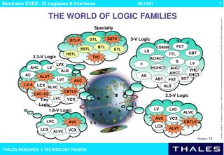
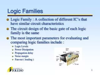
Logic Family • A group of Compatible ICs with the same Logic Levels , using same supply voltages for performing various logic functions, and have been fabricated using specific circuit configuration is referred to as a Logic Family • Logic Families are classified as • Bipolar - fabricated using bipolar devices such as a B.J.Transistors • These can be further classified as • Saturated - Ex. TTL (Transistor Transistor Logic) , RTL , DTL, • Nonsaturated - Ex. Schottky TTL , ECL (Emitter coupled Logic) • Uni polar - fabricated using unipolar devices such as MOSFETs • Can be further divided as • PMOS • NMOS • CMOS
TTL NAND Gate (Basic Gate) + Vcc RB1 4 K IB1 Rc2 1.4 K Rc3 4k B1 Load Gates B2 Y T2 T1 IC3 IB3 A B C T3 Co Inputs B3 RE2 1 K
Operation of TTL Gate • Case I – At least 1 input is Low • B-E junction of T1 is Forward Biased (Vbe=0.7V), therefore Vb1 ~ 0.2 V + 0.7 V = 0.9 V • For T2 & T3 to be conducting • Vb1 must be at least = 0.6V (B-C junction of T1) + Vbe2 + Vbe3 = 1.6V • Since Vb1(0.9V) < 1.6V , the transistors T2 & T3 are Cut Off. • Hence O/P Y = V(1) =Vcc • Case II – All inputs are High • B-E junction of T1 is Reverse Biased , hence Vb1 • Assuming T2 & T3 both to be saturated ,then Vc1 = VBE2sat + VBE3sat = 0.8V+0.8V= 1.6 V • As B1 is connected to Vcc through Rb1 & Vc1=1.6 V , C-B junction of T1 is Forward biased & Ic1 flows in reverse direction driving T2 & T3 in saturation as assumed . • Therefore O/P Y = V(0) = 0.2V
Operation of TTL Gate (contd...) • Case III – All inputs are High & one input Goes Low • T1 starts conducting & Vb1 drops to 0.9 V. At this point T2 & T3 are still in saturation. T2 • & T3 will be turned OFF , only when the stored charges in the T2 & T3 are removed. • Since Vc1= Vb2 = 1.6V , therefore collector base junction of T1 is reverse • biased, and T1 operates in Active region causing large Collector current to flow • in the direction to help fast removal of stored base charge in T2 & T3 . Important Parameters of TTL 7400 VOH =2.4V VOL= 0.4V VIH = 2.0V VIL= 0.8V IOH = -400 µA IOL = 16 mA I IH = 40 µA IIL = -1.6 mA Propagation delay - 10 ns Fan-out 10 = min ( IOH / I IH , IOL / IIL )
There are Seven different series of TTL • Series Prefix Examples • Standard TTL 74- 7402,74193 • High Power TTL 74H- 74H02,74H193 • Low Power TTL 74L- 74L02,74L193 • Schottky TTL 74S- 74S02,74S193 • Low Power Schottky TTL 74LS- 74LS02,74LS193 • Advanced Schottky TTL 74AS- 74AS02,74AS193 • Advanced Low Power • Schottky TTL 74ALS- 74ALS02,74ALS193 • Difference in 74 series 54 series • Operating temp. Range 0 0C to 70 0C -55 0C to +125 0C • Supply Voltage Range 5 ± 0.25 V 5 ± 0.5 V
Specifications of TTL IC families TTL Fan out Capabilities
Important points to remember : • The input & Output Voltage Specifications are compatible for each of the TTL series Hence it is possible to use any mix of ICS of these series • Input output Current Specifications are compatible for each of the TTL series • The Low power dissipation Series L,LS,ALS have minimum power requirements & are suitable for battery operated devices. • ALS series also has the minimum propagation delay • H series has low propagation delay but requires maximum power • S & AS series have very low propagation delay. AS series is low power , fast series
+ Vcc IC4 Rc2 1.4 KΩ Rc4 (100Ω) RB1 4 KΩ IB1 B4 B1 T4 B2 T2 T1 Y C2 Load Gates A B C Inputs IB3 RE2 1 KΩ T3 Co B3 Active Pull up or Totem pole Output
Operation of Totem-pole Output or Active Pull-up TTL Gate When O/P Y is in LOW state , transistor T4 & the diode D are Cut-off. As T2 & T3 are in saturation Vc2 = Vb4 = VBE3 sat + VCE2sat = 0.8V + 0.2V = 1.0V Since Vout = 0.2V , the voltage drop across T4 & diode D = 1.0 V – 0.2V = 0.8V This drop is insufficient to start conduction in T4 & Diode D, hence both are Cut-off When O/P makes transition from LOW to HIGH , transistor T4 enters into Saturation, & supplies current for charging of Output capacitor Co with a small Time Constant. This current IC4 is = (VCC - VCE4 sat – VD – Vo) / RC4 =( 5 – 0.2 – 0.7 – 0.2)/0.1 = 39 mA T4 is in saturation if hFE > 16.5 The Output Voltage Vo exponentially with Time constant = ( RC4 + RCS4 + Rf ) . Co As Vo the base current & collector current of T4 bringing T4 eventually out of conduction V(1) = Vcc – Vγ(T4) - Vγ (diode) = 5 – 0.5 -0.6 = 3.9 V Now if all input go HIGH , T2 is turned ON , T4 & diode D goes OFF & T3 conducts The Capacitor Co discharge through T3 & as Vo approaches V(0) , T3 enters into saturation
Note that Ic4 = 39 mA when the output changes from V(0) to V(1) and the base current IB4 = 2.4 mA Thus maximum current of 39 + 2.4 = 41.4 mA . Is drawn from Power Supply when output changes from V(0) to V(1) This current spike generates Noise in the Power supply & increases Power dissipation Wired AND Must not be used with Totem-pole output circuit due to large current spike during transition from V(0) to V(1) (41 mA) TTL gate with Open Collector output can be used for Wired –AND connections Open Collector Output The basic standard TTL NAND gate with RC3 of T3 missing is the TTL with Open Collector Output
Unconnected inputs If any of the inputs are left un connected , they are treated as Logical 1 Clamping Diodes Used to Suppress ringing caused from fast voltage transitions found in TTL B1 T1 C2 A B C Clamping diodes
C B E D C B E Schottky TTL Gate The Speed of TTL is limited mainly by the turn –off time delay involved when transistor makes transition from saturation to Cut-off. This can be eliminated bym replacing all the transistors of TTL gate by Schottky transistors The transistors are prevented from entering saturation , hence saving of turn-off time. Propagation delay = 2 ns. as compared 10 ns of standard TTL Schottky Transistor storage delay time can be reduced by preventing transistor from going into saturation Symbol A Schottky diode D is connected between base & collector of a transistor as shown. When transistor is in active region D is reverse biased. Diode conducts when B-C junction voltage falls to 0.4 V & thus does not allow Collector voltage of transistor to fall lower than 0.4 V below base voltage . The collector junction is not sufficiently forward biased to enter into saturation
+Vcc S2 G2 T2 (p-channel) D2 D Vi G D1 T1 (n-channel) G1 S1 CMOS Logic Family A complementary MOSFET (CMOS) is obtained by connecting a p-channel & an n-channel MOSFET in series. Drains are tied together & the Output is taken at the Common Drain. Input is applied at the common Gate formed by connecting 2 Gates together as shown When Vi= Vcc T1 turns ON (VGS1 > VT) and CMOS Inverter ID T2 is OFF Since VGS2 =0. Hence VO= 0 . ID is negligible When Vi= 0, T1 turns OFF (VGS1 < VT) and T2 is ON Since |VGS2| > |VT|. The Output voltage Vo= Vcc & ID is again small. In either Logic state the power dissipation is low as PD = VCC X OFF state leakage drain Current Vo
+Vcc T4 A T3 Vo Y=A.B T2 T1 B A 2- input CMOS NAND Gate
+Vcc T4 A T3 B T2 T1 A 2-input CMOS NOR Gate Y=A+B Logic Symbol A Y B
TG CMOS Transmission Gate Is used to control the transmission of Signal from pt. A to pt. B. The circuit is as shown C C T2 A B A B T1 C C A CMOS transmission Gate is controlled by gate voltages C & C . Assume C=1 If A= V(1) , then T1 is OFF & T2 conducts in the ohmic region as there is no voltage applied at the drain. Therefore T2 acts as a small resistance connecting the output to input & B=A=V(1). Similarly if A=V(0) then T2 is OFF & T1 conducts connecting output to input & A=B=V(0) It can also be shown that if C=0 , the transmission is not possible Gate control input C is binary while A & B can be either digital or analog voltage between V(0) & V(1) Noise Margin Considerably higher than that of TTL ICs. CMOS devices have wide Supply voltage range & Noise Margin increases with the Supply voltage VCC. Typically = 0.45 VCC
Wired – Logic Wired Logic must not be used with CMOS Logic circuits CMOS gates with Open drain output can be used for Wired AND operation. In this the drain of the output transistor (n-channel) is available outside , p-channel load does not exist . The resistance is connected externally. 74C00 / 54C00 CMOS series 74C00 / 54C00 CMOS series are the 2 commonly used CMOS series ICs.
Important points to remember : 54C/74C Series is pin to pin , function for function equivalent of 54/74 TTL family & hence is popular. Operating Temp. Range: 74C Series : - 400 C to + 850 C 54C Series : - 550 C to + 1250 C Operating Voltage Range : 3 V to 15 V 74 HC : High Speed CMOS Series 74HCT : High Speed, TTL compatible CMOS Series 74AC/ 74ACT : advanced / advanced , TTL compatible CMOS Series : Are Very fast and have high current sinking capabilities 74HCT / 74ACT : Can be easily used along with TTL ICs for Optimum System design from point of view of Speed, power dissipation, noise margin, cost etc While driving same series : 74 HC / 74HCT Fan out : 20 74 AC / 74ACT Fan out : 50 While driving TTL series : As Fan out = min ( IOH (CMOS) / I IH (TTL) , IOL(CMOS) / IIL(TTL) ) TTL Table of Specifications must be referred for IIH(TTL) & IIL(TTL) .
Unconnected Inputs CMOS devices have very high input resistance & even a small static charge flowing can develop a dangerously high voltage. This may damage insulation layer of the device & person handling it. Therefore CMOS IC pins should not be left un connected Even for storage Aluminium foil should be used so that all IC pins will be shorted together avoiding a voltage development between pins. Interfacing CMOS & TTL For Optimum performance devices of more than one Logic family can be used, taking advantage of superior characteristics of each family. Such as CMOS – Low power dissipation & TTL for high speed When CMOS needs to drive TTL in such a mix of Logic families, for such arrangement to operate properly the following conditions must be satisfied. VOH (CMOS) ≥VIH (TTL) ----------(1) VOL (COMS) ≤ VIL (TTL) ----------(2) -IOH (CMOS) ≥ N IIH (TTL) ----------(3) IOL(CMOS) ≥ - N IIL (TTL) ----------(4)
TTL TTL CMOS TTL The interface diagram is shown From the table we observe condition 1 & 2 are always satisfied . The Noise Margins when 74ACT is driving 74ALS gates are : Δ 1 = 3.76 – 2.0 = 1.76 V Δ0 = 0.8 – 0.37 = 0.43 V The condition 3 & 4 are always satisfied for 74HC/HCT/74AC/84ACT series . The value of N is different for them. For 74ACT driving 74ALS gates is 240 For 74C driving 74L N=2, 74C driving 74ALS N=3 , but 74C driving other members than 74LS & 74ALS condition 4 is not satisfied . This difficulty is overcome by using CMOS buffers having adequate available output current.
TTL driving CMOS When TTL needs to drive CMOS, for such arrangement to operate properly the following conditions must be satisfied. VOH (TTL) ≥VIH (CMOS) ---------------(1) VOL (TTL) ≤ VIL (CMOS) ----------------(2) -IOH (TTL) ≥ N IIH (CMOS) --------------- (3) IOL(TTL) ≥ - N IIL (CMOS) -------------- (4) CMOS CMOS TTL CMOS
TTL driving CMOS (contd…) All above conditions are satisfied for 74HCT & 74ACT series for high value of N. Thus these two series are TTL compatible. But in case of 74C/74HC/74AC series the first equation is not satisfied. Therefore a circuit modification is used to raise VOH (TTL) above 3.5 V by connecting a resistance ( ≈ 2kΩ) between points P & VCC as shown in figure. This resistance acts as a passive pull up, pulling voltage at P by charging a capacitor CO present between P & Ground terminal to higher value (≈VCC) after T4 of TTL becomes non-conducting VCC 2 KΩ P CO TTL CMOS
TRI-STATE LOGIC • In complex digital systems such as Microprocessors, a number of Gates outputs are required to be connected to a common line referred to as a Bus, which in turn is required to drive a number of gates inputs. • When number of gate outputs are to be connected to the Bus, some difficulties arise as • Totem pole outputs can’t be connected together because of very large current drain from supply and consequent heating of IC • Open-Collector outputs though can be connected together with common collector resistance externally, but it causes loading & affects speed of Operation. • Special circuits are developed to overcome this problem. • In these circuits there is one more state of output , referred to as the third state or High impedance state, in addition to HIGH & LOW states. • These circuits are called TRI-STATE Logic • The TSL Inverter (NOT Gate) circuit, truth table & Symbol are shown next
T5 T4 Control Y T2 Data Output T1 T3 Data Input TSL NOT Gate (Inverter) + Vcc When control input is 0 (LOW), the drive is removed from T3 & T4. Hence both T3 & T4 are cut-off & the Output is in third state (High Impedance) When the control input in 1 (HIGH) , the Output is Logic 1 if the data input is 0 & it is Logic 0 if the data input is 1.(NOT Gate)
Data input Data Output Control TSL NOT Gate (Inverter) contd…. Logic Symbol : Truth Table:
Buffer Buffer is a circuit or Gate that can drive a substantially higher number of gates or other loads. It is also known as a Buffer driver Tri-state buffer: Symbol : Truth Table: Data input Data Output Control input Enable
Logic Symbol CMOS Buffer Circuit diagram Data input Data Output +Vcc Enable Enable G2 D Q2 OUT D G1 A C Q1 B