Device Specifications and Logic Families
220 likes | 844 Views
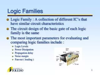
Device Specifications and Logic Families. Lecture Overview. IC Categories Voltage Levels Noise Margin Logic Families. Overview Continued. Power vs. Speed Data Sheets Recommended Operating Conditions Electrical Characteristics Switching Characteristics Fanout. IC Categories. Input

Device Specifications and Logic Families
E N D
Presentation Transcript
Lecture Overview • IC Categories • Voltage Levels • Noise Margin • Logic Families
Overview Continued • Power vs. Speed • Data Sheets • Recommended Operating Conditions • Electrical Characteristics • Switching Characteristics • Fanout
Input Voltage Output Voltage Maximum 5.0 V 5.0 V Maximum HIGH HIGH 4.0 V 4.0 V Typical 3.5 V 3.0 V 3.0 V 2.4 V 2.0 V 2.0 V 2.0 V Undefined Region Undefined Region 1.0 V 1.0 V 0.8 V 0.4 V LOW LOW Minimum 0.0 V 0.0 V Minimum Typical 0.1 V TTL Voltage Levels
Input Voltage Output Voltage Maximum 5.0 V 5.0 V Maximum HIGH HIGH 4.0 V 4.0 V Typical 3.5 V 3.0 V 3.0 V 2.4 V 2.0 V 2.0 V Noise Margin (0.4 V) 2.0 V Undefined Region Undefined Region 1.0 V 1.0 V 0.8 V Noise Margin (0.4 V) 0.4 V LOW LOW Minimum 0.0 V 0.0 V Minimum Typical 0.1 V TTL Noise Margins
Input Voltage Output Voltage Maximum 5.0 V 5.0 V Maximum 4.9 V HIGH HIGH 4.0 V 4.0 V 3.5 V 3.0 V 3.0 V Undefined Region Undefined Region 2.0 V 2.0 V 1.0 V 1.0 V 1.0 V LOW LOW Minimum 0.0 V 0.0 V Minimum 0.1 V CMOS Voltage Levels
Input Voltage Output Voltage Maximum 5.0 V 5.0 V Maximum 4.9 V HIGH HIGH 4.0 V 4.0 V Noise Margin (1.4 V) 3.5 V 3.0 V 3.0 V Undefined Region Undefined Region 2.0 V 2.0 V 1.0 V 1.0 V 1.0 V LOW Noise Margin (0.9 V) LOW Minimum 0.0 V 0.0 V Minimum 0.1 V CMOS Noise Margins
Propagation Delay Switching Characteristics
Fanout How Many Gates Can Be Connected To One Output ?
II IO VI VO Fanout • The fanout of a logic gate is the number of inputs that a gate can drive without exceeding its worst-case loading specifications. • Fanout must be examined for both possible output states. • TTL input or output lead is defined to be positive if the current actually flows into the lead, and negative if the current flows out of the leads.
II IO VI VO Electrical Characteristics
Current Drive Capability IILMAX : The maximum current that an input requires to pull it LOW. Since current flows out of a TTL input in the LOW state, IILMAX has a negative value. Approximately –0.4 mAmps for most TTL inputs. IIHMAX : The maximum current that an input requires to pull it HIGH. Since current flows into a TTL input in the HIGH state, IIHMAX has a positive value. Approximately -20uAmps for most TT inputs.. IOLMAX : The maximum current that the output can sink in the LOW state while still maintaining an output voltage no greater then VOLMAX. Since current flows into the output, IOLMAX has a position value. Approximately 8 mAmps for most TTL outputs. IOHMAX : The maximum current that the output can source in the HIGH state while still maintaining an output voltage no less then VOHMIN. Since current flows out of the output, IOHMAX has a negative value. Approximately –400 uAmps for most TTL inputs.
Asymmetrical TTL Outputs High Output IOHMAX = -400 uAmps IOHMAX IIHMAX = 20uAmps FanoutHIGH = 400uAmp / 20 uAmp = 20 Low Output IOLMAX = 8 mAmps IOHMAX IILMAX = - 0.4 mAmps FanoutLOW = 8 mAmp / 0.4 mAmp = 20