Download
1 / 20
200 likes | 395 Views
Explore the development of digital logic families from Diode Logic to TTL to ECL and CMOS, considering integration levels and key characteristics. Learn about Moore's Law, TTL evolution, and CMOS power requirements. Understand noise margins, propagation delays, and gate ratios.

E N D
Digital Logic Families PHYS3360/AEP3630 Lecture 26
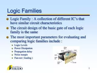
Overview • Integration, Moore’s law • Early families (DL, RTL) • TTL • Evolution of TTL family • ECL • CMOS family and its evolution • Overview
Integration Levels • Gate/transistor ratio is roughly 1/10 • SSI < 12 gates/chip • MSI < 100 gates/chip • LSI …1K gates/chip • VLSI …10K gates/chip • ULSI …100K gates/chip • GSI …1Meg gates/chip
Moore’s law • A prediction made by Moore (a co-founder of Intel) in 1965: “… a number of transistors to double every 2 years.”
In the beginning… • Diode Logic (DL) • simplest; does not scale • NOT not possible (need an active element) = • Resistor-Transistor Logic (RTL) • replace diode switch with a transistor switch • can be cascaded • large power draw =
was… • Diode-Transistor Logic (DTL) • essentially diode logic with transistor amplification • reduced power consumption • faster than RTL = Saturating inverter DL AND gate
Logic families: V levels VOH(min) – The minimum voltage level at an output in the logical “1” state under defined load conditions VOL(max) – The maximum voltage level at an output in the logical “0” state under defined load conditions VIH(min) – The minimum voltage required at an input to be recognized as “1” logical state VIL(max) – The maximum voltage required at an input that still will be recognized as “0” logical state VIH VOH VIL VOL
Logic families: I requirements IOH – Current flowing into an output in the logical “1” state under specified load conditions IOL – Current flowing into an output in the logical “0” state under specified load conditions IIH – Current flowing into an input when a specified HI level is applied to that input IIL – Current flowing into an input when a specified LO level is applied to that input IOH IIH IOL IIL VIH VOH VIL VOL
Logic families: fanout Fanout: the maximum number of logic inputs (of the same logic family) that an output can drive reliably DC fanout = min( )
Logic families: propagation delay TPD,HL TPD,LH TPD,HL – input-to-output propagation delay from HI to LO output TPD,LH – input-to-output propagation delay from LO to HI output Speed-power product: TPD Pavg
Logic families: noise margin HI state noise margin: VNH = VOH(min) – VIH(min) LO state noise margin: VNL = VIL(max) – VOL(max) Noise margin: VN = min(VNH,VNL) VNH VNL
TTL • Bipolar Transistor-Transistor Logic (TTL) • first introduced by in 1964 (Texas Instruments) • TTL has shaped digital technology in many ways • Standard TTL family (e.g. 7400) is obsolete • Newer TTL families still used (e.g. 74ALS00) • Distinct features • Multi-emitter transistors • Totem-pole transistor arrangement • Open LTspice example: TTL NAND… 2-input NAND
TTL evolution • Schottky series (74LS00) TTL • A major slowdown factor in BJTs is due to transistors going in/out of saturation • Shottky diode has a lower forward bias (0.25V) • When BC junction would become forward biased, the Schottky diode bypasses the current preventing the transistor from going into saturation
TTL family evolution Legacy: don’t use in new designs Widely used today
ECL • Emitter-Coupled Logic (ECL) • PROS: Fastest logic family available (~1ns) • CONS: low noise margin and high power dissipation • Operated in emitter coupled geometry (recall differential amplifier or emitter-follower), transistors are biased and operate near their Q-point (never near saturation!) • Logic levels. “0”: –1.7V. “1”: –0.8V • Such strange logic levels require extra effort when interfacing to TTL/CMOS logic families. • Open LTspice example: ECL inverter…
CMOS • Complimentary MOS (CMOS) • Other variants: NMOS, PMOS (obsolete) • Very low static power consumption • Scaling capabilities (large integration all MOS) • Full swing: rail-to-rail output • Things to watch out for: • don’t leave inputs floating (in TTL these will float to HI, in CMOS you get undefined behaviour) • susceptible to electrostatic damage (finger of death) • Open LTspice example: CMOS NOT and NAND…
CMOS/TTL power requirements • TTL power essentially constant (no frequency dependence) • CMOS power scales as f C V2 • At high frequencies (>> MHz) CMOS dissipates more power than TTL • Overall advantage is still for CMOS even for very fast chips – only a relatively small portion of complicated circuitry operates at highest frequencies supply volt. frequency eff. capacitance
CMOS family evolution obsolete General trend: • Reduction of dynamic losses through successively decreasing supply voltages: 12V 5V 3.3V 2.5V 1.8V • CD4000LVC/ALVC/AVC • Power reduction is one of the keys to progressive growth of integration
TTL Overview Logic Family Noise Margin TPD Trise/fallVIH,min VIL,max VOH,min VOL,max • Values typical for Vcc/Vdd = 5V • When interfacing different families, pay attention to their input/output voltage, current (fanout) specs. CMOS