Download
1 / 23
230 likes | 342 Views
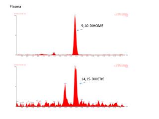
This project focuses on creating reliable sensing equipment for measuring current and voltage in plasma environments exceeding 500V and 10MHz. Existing commercial probes do not meet both frequency and voltage specifications, leading to the need for high-impedance, homebrew solutions. The design leverages HFSS simulations to address parasitic issues and optimize performance, while also allowing for in-line sensor integration. Future work will examine enhancements, budgets, and potential for experiments in plasma stability and waveform analysis.

E N D
Plasma E- Measurement Brian DeHerrera John Purcell JaberAssiri
Introduction • Purpose • Problems • HFSS Simulation • Current Design • Voltage Divider • Future Work & budget • Conclusion Outline
Create reliable current and voltage sensing equipment to work in common plasma ranges • >500V • >10MHz • Create more reliable plasma for experiments • Control line impedance • Measure waveform being transmitted to plasma probe Purpose
No commercially available probes • Can meet some specifications, but not both frequency and desired voltage • Not trivial to create homebrew probe • Needs to be high impedance • Parasitic Problems
Draw Model • Assign Boundary Conditions • Assign Excitation Ports (inputs) • Analyze • Generate Reports HFSS Simulation
Modeled design off of AE’s Z-Scan Benefits: • Parasitic are minimized • Sensor can be added in-line with plasma system Concerns: • EMI design: both shielding outside noise and reducing leakage • Semi-complicated design • Need to machine parts Current Design: Coax
Why a V-D? Voltage Divider
Conditions: • R1+R2>= 2M Ohm & C1+C2<10p F Voltage Divider
Conditions: • R1*C1=R2*C2 • If (R1*C1)> (R2* C2) Voltage Divider
Conditions: • R1*C1=R2*C2 • If (R1*C1)<(R2* C2) Voltage Divider
Conditions: • R1*C1=R2*C2 Voltage Divider
From: • R1+R2>= 2M Ohm & C1+C2<10pF & • R1*C1=R2*C2 • Therefore: • R1= 10M ohm, R2= 100k ohm • C1= .1pF , C2= 10pF Voltage Divider
Purposes & problems • HFSS Simulation • Current Design • Voltage Divider • Future Work & budget Conclusion
Questions ?? Thank you