Download
1 / 17
170 likes | 297 Views
Receiver Mezz. Card. Bar Code. Front. Adder. mezz link cards. EISO. SORT ASICs (w/heat sinks). Input. BSCAN ASICs. EISO. DC-DC. 7/25 tested (18). 153/154 Tested (126). Back. Oscillator. Bar Code. Phase ASIC. PHASE ASICs. Clock Input. Clock delay adjust. BSCAN

E N D
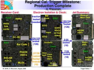
Receiver Mezz. Card Bar Code Front Adder mezz link cards EISO SORT ASICs (w/heat sinks) Input BSCAN ASICs EISO DC-DC 7/25 tested (18) 153/154 Tested (126) Back Oscillator Bar Code Phase ASIC PHASE ASICs Clock Input Clock delay adjust BSCAN ASICs MLUs DC-DC Converters BSCAN ASICs Sort ASICs Regional Cal. Trigger Milestone:Production Complete- U. Wisconsin • Receiver Card: Electron Isolation & Clock: Jet/Summary: fraction tested (needed) EISO Front 124/153 tested (126) 3/25 tested (18) Clock Back (27/28 Custom Backpl Tested) (18)
RCT Full Crate Operating at CERN- U. Wisconsin • Used for HCAL, ECAL, SLB, Global Calorimeter Trigger integration tests • Located in Electronics Integration Center in Bat. 904 - more tests planned (later slides) x 18 Rear: Receiver Cards Front: Electron, Jet, Clock Cards
CSC Trigger Muon Port Card & Sector Processor • Muon Port Card (Rice): • 6 built w/FPGA mezzanines, fully tested in beam, in radiation, in crate w/ 7 Trigger Motherboards connected to Sector Processor • Final production done (tested 47) • Total needed: 60 (75 incl. spares) • Sector Processor (Florida): • PPP built & tested in structured beam & full system test (next slide) • In production (1st 2 made) • Total needed: 12 VME Interface (glue logic) XilinxVirtex-2 800 User I/O Optomodules GTLP Receivers TLK2501 serializers Mezzanine card 15 X 1.6 Gb/s optical links from MPC
CSC Muon Sorter- Rice • Rice MS sorts SP muons and transmits to Vienna Global Muon Trigger • Integration Test successful in Jan. ‘05 in Vienna Muon Sorter Board
CSC Trigger Full Chain Test- Florida, Rice, UCLA, March’05 This is 1/60 of full CSC Trigger w/Track-Finder crate 100% loaded into the Muon Sorter MPCCCB Track-Finder Crate: SP CCB MS 5 TMB 4 TMB Fully Loaded Peripheral Crate tester cards provide full 12 SP input to MS Results in reinforced grounding for better signal quality on production TF backplane & cards
Trigger Commissioning Plans • Operate fully functional trigger electronics at CERN • Employed in myriad tests & preparation activities • Tests in Electronics Integration Center • Labs & row of racks for all electronicssubsystems • Test interfaces & integration as much as possible before move to USC55 • Cosmic Challenge in SX5 • Test multiple triggercomponents with multipledetector components duringthe magnet test. • Verify trigger functions &interfaces w/detectors onsurface • Installation in Underground CountingRoom (USC55) • Expect start by Nov 30 ‘05 -- “ready for crates” • Racks & Infrastructure installed, cooling operational USC55 UndergroundCounting Room
Trigger Install/Commission:Electronics Integration Center: Prevessin 904 • Assemble one each of critical racks in central trigger core in underground counting room Electronics Labs trigger & electronics integration racks Test/integrate triggerelectronics in EIC beforeuse in Cosmic Challengeor installation in USC55 Started April 18
HCAL-SLB-RCT Integration in EIC- Maryland, Lisbon, Wisconsin • Sent synchronous jet data from HCAL HTR Cards thru 6 SLB over 10m copper 4Gb/s Vitesse Links to 6 Regional Calorimeter Trigger Receiver Mezzanine cards, thru Receiver Cards, Backplane and Jet Summary Card to Jet Capture Card recording output of 256 crossings. See output jets on all channels in expected crossings.
CSC trigger in cosmic challenge - Florida & Rice • Set-up in SX5 as operated during 2004 beam tests • Connected 6 chambers in ME+2 & ME+3 20° slice on YE+2 SP CCB CSC Track-Finder will provide a cosmic muon trigger based on a coincidence of LCTs in two or more disks
USC55 Trigger Schedule Overview • Four phases of activity in USC55: • Installation, Detector Integration, Central Integration, Commission
Trigger Install Schedule - I • Install/Commission Trig. Crates: Dec ‘05 - Apr ‘06 • Tested Trigger Crates installed, re-tested, interconnected, inter-synchronized • Regional and Global Detector trigger systems integrated with each other and Global Trigger • Integrate w/Detector Elect.: May ‘06 - Oct ‘06 • Cal Trig connected to E/HCAL USC55 electronics • Muon Triggers connected to optical fibers carrying trigger data from detector • Global Trigger connected to TTC distribution system • Operation with Local DAQ
Trigger Install Schedule - II • Integrate w/Central Trig. & DAQ Nov ‘06 - Apr ‘07 • Subset of triggers available to detectors in UXC55 • Dedicated testing with individual detectors • Detailed synchronization testing of all systems • Testing with Central DAQ • System Commissioning May ‘07 - Jun ‘07 • Full capability of trigger system available • Tests with all detectors and trigger operating simultaneously together and partitioned • Trigger and DAQ can operate in 8 separate partitions • Ready for single beam commissioning, Jul ‘07 • Beam-gas synchronized triggers • Halo muon events (see following slides)
Preparing for Operationbefore beam & after install/commission • Run as much of CMS as possible integrated with TriDAS for as long as possible to shake out problems. • Run for long periods of time with artificially generated data of as high a volume a possible loaded as close to the front ends as we can manage with as high a trigger rate as we can handle. • This type of continuous "stress-testing" should help us to make the system robust. • Also run for long periods of time with cosmic triggers • Download simulated data in both the readout and trigger streams • See if we can pass these all the way to yield triggers and physics signals on tape.
Trigger Commissioning Phaseswith first collisions • 1. Synchronization & Trigger testing/evaluation • Determine that data is being properly set up (e.g. synchronized), triggered and transported to farm nodes. • 2. Technical validation of subdetector data • Determine from detector data written to farm nodes that detectors are indeed being read out properly and if the data is indeed correct technically • 3. Evaluation/calibration/validation of subdetector data • Study the subdetector data calibration and performance to validate its content for physics analysis • 4. Evaluation of data by physics groups. • Make basic physics plots of detector data to validate performance • 5. Feedback from Physics Groups. • Transport of min-bias data to the remote Tier-1 centers for input into the simulation and regeneration of our simulation samples • Calculation of trigger efficiencies and feedback to the trigger group on physics problems with the day 1 trigger set.
Commissioning TriDAS Modes • Normal Mode • Trigger rate at 50 kHz (evolves from 12.5 50 75 100 kHz) • “Safe” Mode • Trigger rate < 10 kHz • Level-1 Latency 3.2 s (128 bunch crossings - bx) • “Un-buffered” Trigger Rule • Each L1A separated by at least 8.75 s • Assures that all detectors are read out before next L1A - no storage of additional events after each L1A. • Limit set by tracker & presh., deadtime of 9% @ L1A rate of 10 kHz. • “Single Step” Mode • Trigger rate “low” • Level-1 Latency 3.2 s (128 bunch crossings - bx) • “Handshake” Trigger Rule: • After each L1A, Global Trigger System raises busy and waits for DAQ, to lower the busy after the event has been successfully read out. • Large deadtime, only usable for debugging and initial commissioning.
Initial Trigger Menu • Level-1 Trigger Totally Open • Calorimeter low ET or any muon (no PT cut) • Other candidate triggers for later running are active for diagnostic and study purposes • Continue Halo Muon & Cosmic triggers • Test Triggers • Dedicated runs and possible operation during abort gaps to verify detector functionality and synchronization.
Summary - Trigger • Trigger Hardware: • Finished with, in or about to start production • Trigger Integration • Much testing already done • Program of Electronics Integration Center Tests • Trigger Program for Cosmic Challenge • Trigger Commissioning • Realistic plan in place starting with USC55 occupancy in December • Operation with downloaded simulated data in USC55 • Orderly connection and checkout with subsystems, central systems • Operations & testing w/o beam (downloaded & cosmic) planned until startup • Use of single beams for halo muon triggers & beam-gas events • Plan developed for first data run operations • 5 Phases: • synchronization & testing, technical validation of data transport, data content validation, data physics evaluation, physics feedback • Totally open trigger menu & test triggers