Download
1 / 9
140 likes | 703 Views
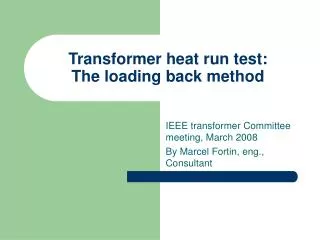
Transformer heat run test: The loading back method. IEEE transformer Committee meeting, March 2008 By Marcel Fortin, eng., Consultant. Standard Requirement: C57.12.90 clause 11. Tests shall be made by one of the following methods: a) Actual loading b) Simulated loading

E N D
Transformer heat run test: The loading back method IEEE transformer Committee meeting, March 2008 By Marcel Fortin, eng., Consultant
Standard Requirement: C57.12.90 clause 11 • Tests shall be made by one of the following methods: • a) Actual loading • b) Simulated loading • 1) The short-circuit method, in which appropriate total losses are produced by the effect of short-circuit current • 2) The loading back (opposition) method, in which rated voltage and current are induced in the transformer under test
Duplicate (not nessary) transformers may be tested by connecting their respective high-voltage and low-voltage windings in parallel (see Figure 27 and Figure 28). Transformers shall be tested with the combination of connections and taps that give the highest average winding temperature rise. This will generally involve those connections and taps resulting in the highest losses. Standard Requirement: C57.12.90 clause 11
Loading back method • Transformer 1: transformer under test • Transformer 2: « source » transformer • S1: variable source, provides essentially the total iron losses • S2: variable source, provides essentially the copper losses
Loading back method Tranformer 1 • P1 : nomiral kVA • Ip1: nominal primary current • Is1: nominal secondary current • Up1: nominal primary voltage • Us1: nominal secondary voltage • Iz1: percentage impedance • N1: Up1/ Us1
Loading back method Tranformer 2 requirements • P2 P1 • Ip2 Ip1 • Is2 Is1 • Up2 Up1 • Us2 Us1 • Iz2: percentage impedance • n2 = n1 (Iz1+Iz2) (base power: P1)
Loading back method Source 1 requirement • Variable source • Voltage range: 0 to Us1 • Nominal current: enough to feed the total magnetizing current.
Loading back method Source 2 requirement • Variable source • Voltage range: 0 to total Iz voltage drop • Nominal current Ip1