Perception
4. Perception. Sensors Uncertainty Features. "Position" . Localization. Cognition. Global Map. Environment Model. Path. Local Map. Real World. Perception. Motion Control. Environment. 4.1. Example HelpMate, Transition Research Corp. 4.1. Example B21, Real World Interface. 4.1.

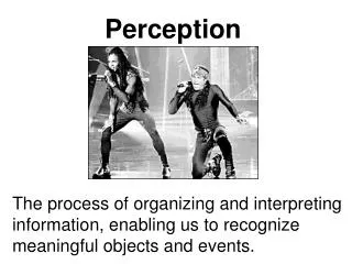
Perception
E N D
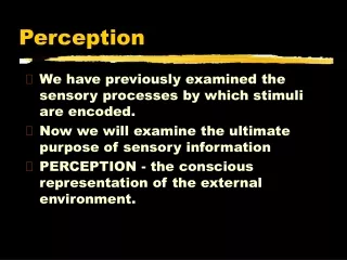
Presentation Transcript
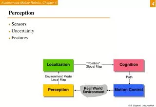
4 Perception • Sensors • Uncertainty • Features "Position" Localization Cognition Global Map Environment Model Path Local Map Real World Perception Motion Control Environment
4.1 Example HelpMate, Transition Research Corp.
4.1 Example B21, Real World Interface
4.1 Example Robart II, H.R. Everett
4.1 Savannah, River Site Nuclear Surveillance Robot
4.1 BibaBot, BlueBotics SA, Switzerland Omnidirectional Camera Pan-Tilt Camera IMUInertial Measurement Unit Sonar Sensors Emergency Stop Button Laser Range Scanner Wheel Encoders Bumper
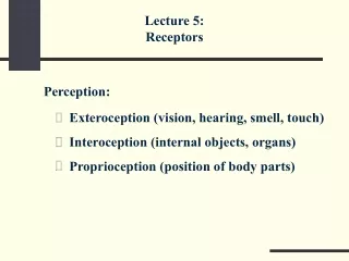
4.1.1 Classification of Sensors • Proprioceptive sensors • measure values internally to the system (robot), • e.g. motor speed, wheel load, heading of the robot, battery status • Exteroceptive sensors • information from the robots environment • distances to objects, intensity of the ambient light, unique features. • Passive sensors • energy coming for the environment • Active sensors • emit their proper energy and measure the reaction • better performance, but some influence on envrionment
4.1.1 General Classification (1)
4.1.1 General Classification (2)
4.1.2 Characterizing Sensor Performance (1) Measurement in real world environment is error prone • Basic sensor response ratings • Dynamic range • ratio between lower and upper limits, usually in decibels (dB, power) • e.g. power measurement from 1 Milliwatt to 20 Watts • e.g. voltage measurement from 1 Millivolt to 20 Volt • 20 instead of 10 because square of voltage is equal to power!! • Range • upper limit
4.1.2 Characterizing Sensor Performance (2) • Basic sensor response ratings (cont.) • Resolution • minimum difference between two values • usually: lower limit of dynamic range = resolution • for digital sensors it is usually the A/D resolution. • e.g. 5V / 255 (8 bit) • Linearity • variation of output signal as function of the input signal • linearity is less important when signal is after treated with a computer • Bandwidth or Frequency • the speed with which a sensor can provide a stream of readings • usually there is an upper limit depending on the sensor and the sampling rate • Lower limit is also possible, e.g. acceleration sensor
4.1.2 error In Situ Sensor Performance (1) Characteristics that are especially relevant for real world environments • Sensitivity • ratio of output change to input change • however, in real world environment, the sensor has very often high sensitivity to other environmental changes, e.g. illumination • Cross-sensitivity • sensitivity to environmental parameters that are orthogonal to the target parameters • Error / Accuracy • difference between the sensor’s output and the true value m = measured value v = true value
4.1.2 In Situ Sensor Performance (2) Characteristics that are especially relevant for real world environments • Systematic error -> deterministic errors • caused by factors that can (in theory) be modeled -> prediction • e.g. calibration of a laser sensor or of the distortion cause by the optic of a camera • Random error -> non-deterministic • no prediction possible • however, they can be described probabilistically • e.g. Hue instability of camera, black level noise of camera .. • Precision • reproducibility of sensor results
4.1.2 Characterizing Error: The Challenges in Mobile Robotics • Mobile Robot has to perceive, analyze and interpret the state of the surrounding • Measurements in real world environment are dynamically changing and error prone. • Examples: • changing illuminations • specular reflections • light or sound absorbing surfaces • cross-sensitivity of robot sensor to robot pose and robot-environment dynamics • rarely possible to model -> appear as random errors • systematic errors and random errors might be well defined in controlled environment. This is not the case for mobile robots !!
4.1.2 Multi-Modal Error Distributions: The Challenges in … • Behavior of sensors modeled by probability distribution (random errors) • usually very little knowledge about the causes of random errors • often probability distribution is assumed to be symmetric or even Gaussian • however, it is important to realize how wrong this can be! • Examples: • Sonar (ultrasonic) sensor might overestimate the distance in real environment and is therefore not symmetric • Thus the sonar sensor might be best modeled by two modes:- mode for the case that the signal returns directly- mode for the case that the signals returns after multi-path reflections. • Stereo vision system might correlate to images incorrectly, thus causing results that make no sense at all
4.1.3 Wheel / Motor Encoders (1) • measure position or speed of the wheels or steering • wheel movements can be integrated to get an estimate of the robots position -> odometry • optical encoders are proprioceptive sensors • thus the position estimation in relation to a fixed reference frame is only valuable for short movements. • typical resolutions: 2000 increments per revolution. • for high resolution: interpolation
4.1.3 scanning reticle fields scale slits Notice what happen when the direction changes: Wheel / Motor Encoders (2)
4.1.4 Heading Sensors • Heading sensors can be proprioceptive (gyroscope, inclinometer) or exteroceptive (compass). • Used to determine the robots orientation and inclination. • Allow, together with an appropriate velocity information, to integrate the movement to an position estimate. • This procedure is called dead reckoning (ship navigation)
4.1.4 Compass • Since over 2000 B.C. • when Chinese suspended a piece of naturally magnetite from a silk thread and used it to guide a chariot over land. • Magnetic field on earth • absolute measure for orientation. • Large variety of solutions to measure the earth magnetic field • mechanical magnetic compass • direct measure of the magnetic field (Hall-effect, magnetoresistive sensors) • Major drawback • weakness of the earth field • easily disturbed by magnetic objects or other sources • not feasible for indoor environments
4.1.4 Gyroscope • Heading sensors, that keep the orientation to a fixed frame • absolute measure for the heading of a mobile system. • Two categories, the mechanical and the optical gyroscopes • Mechanical Gyroscopes • Standard gyro • Rated gyro • Optical Gyroscopes • Rated gyro
4.1.4 Mechanical Gyroscopes • Concept: inertial properties of a fast spinning rotor • gyroscopic precession • Angular momentum associated with a spinning wheel keeps the axis of the gyroscope inertially stable. • Reactive torque t (tracking stability) is proportional to the spinning speed w, the precession speed W and the wheels inertia I. • No torque can be transmitted from the outer pivot to the wheel axis • spinning axis will therefore be space-stable • Quality: 0.1° in 6 hours • If the spinning axis is aligned with the north-south meridian, the earth’s rotation has no effect on the gyro’s horizontal axis • If it points east-west, the horizontal axis reads the earth rotation
4.1.4 Rate gyros • Same basic arrangement shown as regular mechanical gyros • But: gimble(s) are restrained by a torsional spring • enables to measure angular speeds instead of the orientation. • Others, more simple gyroscopes, use Coriolis forces to measure changes in heading.
4.1.4 Optical Gyroscopes • First commercial use started only in the early 1980 when they where first installed in airplanes. • Optical gyroscopes • angular speed (heading) sensors using two monochromic light (or laser) beams from the same source. • On is traveling in a fiber clockwise, the other counterclockwise around a cylinder • Laser beam traveling in direction of rotation • slightly shorter path -> shows a higher frequency • difference in frequency Df of the two beams is proportional to the angular velocity W of the cylinder • New solid-state optical gyroscopes based on the same principle are build using microfabrication technology.
4.1.5 Ground-Based Active and Passive Beacons • Elegant way to solve the localization problem in mobile robotics • Beacons are signaling guiding devices with a precisely known position • Beacon base navigation is used since the humans started to travel • Natural beacons (landmarks) like stars, mountains or the sun • Artificial beacons like lighthouses • The recently introduced Global Positioning System (GPS) revolutionized modern navigation technology • Already one of the key sensors for outdoor mobile robotics • For indoor robots GPS is not applicable, • Major drawback with the use of beacons in indoor: • Beacons require changes in the environment -> costly. • Limit flexibility and adaptability to changing environments.
4.1.5 Global Positioning System (GPS) (1) • Developed for military use • Recently it became accessible for commercial applications • 24 satellites (including three spares) orbiting the earth every 12 hours at a height of 20.190 km. • Four satellites are located in each of six planes inclined 55 degrees with respect to the plane of the earth’s equators • Location of any GPS receiver is determined through a time of flight measurement • Technical challenges: • Time synchronization between the individual satellites and the GPS receiver • Real time update of the exact location of the satellites • Precise measurement of the time of flight • Interferences with other signals
4.1.5 Global Positioning System (GPS) (2)
4.1.5 Global Positioning System (GPS) (3) • Time synchronization: • atomic clocks on each satellite • monitoring them from different ground stations. • Ultra-precision time synchronization is extremely important • electromagnetic radiation propagates at light speed, • Roughly 0.3 m per nanosecond. • position accuracy proportional to precision of time measurement. • Real time update of the exact location of the satellites: • monitoring the satellites from a number of widely distributed ground stations • master station analyses all the measurements and transmits the actual position to each of the satellites • Exact measurement of the time of flight • the receiver correlates a pseudocode with the same code coming from the satellite • The delay time for best correlation represents the time of flight. • quartz clock on the GPS receivers are not very precise • the range measurement with four satellite • allows to identify the three values (x, y, z) for the position and the clock correction ΔT • Recent commercial GPS receiver devices allows position accuracies down to a couple meters.