Download
1 / 42

E N D
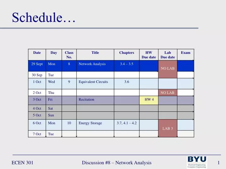
Schedule… Discussion #8 – Network Analysis
Personal Revelation Moroni 10:3-5 3 Behold, I would exhort you that when ye shall read these things, if it be wisdom in God that ye should read them, that ye would remember how merciful the Lord hath been unto the children of men, from the creation of Adam even down until the time that ye shall receive these things, and ponder it in your hearts. 4 And when ye shall receive these things, I would exhort you that ye would ask God, the Eternal Father, in the name of Christ, if these things are not true; and if ye shall ask with a sincere heart, with real intent, having faith in Christ, he will manifest the truth of it unto you, by the power of the Holy Ghost. 5 And by the power of the Holy Ghost ye may know the truth of all things. Discussion #8 – Network Analysis
Lecture 8 – Network Analysis Controlled Sources Superposition Source Transformations Discussion #8 – Network Analysis
Network Analysis • Network Analysis Methods: • Node voltage method • Mesh current method • Superposition • Equivalent circuits • Source transformation • Thévenin equivalent • Norton equivalent Discussion #8 – Network Analysis
Controlled (Dependent) Sources Node and Mesh Analysis Discussion #8 – Network Analysis
+ _ Dependent (Controlled) Sources • Diamond shaped source indicates dependent source • Dependent sources are an important part of amplifiers vs is Discussion #8 – Network Analysis
Controlled Sources • Network analysis with controlled sources: • Initially treat controlled sources as ideal sources • In addition to equations obtained by node/mesh analysis there will be the constraint equation (the controlled source equation) • Substitute constraint equation into node/mesh equations Discussion #8 – Network Analysis
R4 R3 R1 R5 R2 + v – + vout – + – vin – + 2v Controlled Sources • Example1: find the gain (Av = vout/vin) • R1= 1Ω, R2= 0.5Ω, R3 = 0.25Ω, R4 = 0.25Ω , R5 = 0.25Ω Discussion #8 – Network Analysis
+R4– ib +R3 – + R1– R5 R2 + v – + vout – + – vin – + ia 2v ic Controlled Sources • Example1: find the gain (Av = vout/vin) • R1= 1Ω, R2= 0.5Ω, R3 = 0.25Ω, R4 = 0.25Ω , R5 = 0.25Ω Choose mesh analysis – simpler than node analysis • Mesh current directions chosen • Voltage polarities chosen and labeled • Identify n – m (3) mesh currents • ia is independent • ia is independent • ic is independent • Apply KVL around meshes a, b, and c Discussion #8 – Network Analysis
+R4– ib +R3 – + R1– R5 R2 + v – + vout – + – vin – + ia 2v ic Controlled Sources • Example1: find the gain (Av = vout/vin) • R1= 1Ω, R2= 0.5Ω, R3 = 0.25Ω, R4 = 0.25Ω , R5 = 0.25Ω • Apply KVL at nodes a,b, and c Discussion #8 – Network Analysis
+R4– ib +R3 – + R1– R5 R2 + v – + vout – + – vin – + ia 2v ic Controlled Sources • Example1: find the gain (Av = vout/vin) • R1= 1Ω, R2= 0.5Ω, R3 = 0.25Ω, R4 = 0.25Ω , R5 = 0.25Ω • Solve the n – m equations Discussion #8 – Network Analysis
+R4– ib +R3 – + R1– R5 R2 + v – + vout – + – vin – + ia 2v ic Controlled Sources • Example1: find the gain (Av = vout/vin) • R1= 1Ω, R2= 0.5Ω, R3 = 0.25Ω, R4 = 0.25Ω , R5 = 0.25Ω • Solve the n – m equations (Matrices) Discussion #8 – Network Analysis
+R4– ib +R3 – + R1– R5 R2 + v – + vout – + – vin – + ia 2v ic Controlled Sources • Example1: find the gain (Av = vout/vin) • R1= 1Ω, R2= 0.5Ω, R3 = 0.25Ω, R4 = 0.25Ω , R5 = 0.25Ω • Solve the n – m equations (Matrices) Discussion #8 – Network Analysis
+ – vin – + Controlled Sources • Example1: find the gain (Av = vout/vin) • R1= 1Ω, R2= 0.5Ω, R3 = 0.25Ω, R4 = 0.25Ω , R5 = 0.25Ω +R4– • Find the gain ib +R3 – + R1– R5 R2 + v – + vout – ia 2v ic Discussion #8 – Network Analysis
+ – vs Controlled Sources • Example2: Find v1 • vs= 15V, R1= 8Ω, R2= 6Ω, R3 = 6Ω, R4 = 6Ω, ix= vx/3 + vx – R2 R3 ix R1 R4 Discussion #8 – Network Analysis
+ – vs Controlled Sources • Example2: Find v1 • vs= 15V, R1= 8Ω, R2= 6Ω, R3 = 6Ω, R4 = 6Ω, ix= vx/3 • Label currents and voltages (polarities “arbitrarily” chosen) • Choose Node c (vc) as the reference node (vc = 0) • Define remaining n – 1 (2) voltages • va is independent • vb is independent • Apply KCL at nodes a and b + vx – Node b Node a va vb R2 + R3 – ix i2 i3 + R1 – + R4 – i1 i4 vc Node c Discussion #8 – Network Analysis
+ – vs Controlled Sources • Example2: Find v1 • vs= 15V, R1= 8Ω, R2= 6Ω, R3 = 6Ω, R4 = 6Ω, ix= vx/3 • Apply KCL at nodes a and b + vx – Node b Node a va vb R2 + R3 – ix i2 i3 + R1 – + R4 – i1 i4 vc Node c Discussion #8 – Network Analysis
+ – vs Controlled Sources • Example2: Find v1 • vs= 15V, R1= 8Ω, R2= 6Ω, R3 = 6Ω, R4 = 6Ω, ix= vx/3 • Solve the n – 1 – m equations + vx – Node b Node a va vb R2 + R3 – ix i2 i3 + R1 – + R4 – i1 i4 vc Node c Discussion #8 – Network Analysis
+ vx – Node b Node a va vb R2 + R3 – ix i2 i3 + R1 – + R4 – + – vs i1 i4 vc Node c Controlled Sources • Example2: Find v1 • vs= 15V, R1= 8Ω, R2= 6Ω, R3 = 6Ω, R4 = 6Ω, ix= vx/3 • Solve the n – 1 – m equations Discussion #8 – Network Analysis
The Principle of Superposition Discussion #8 – Network Analysis
+ – vs is Superposition Superposition: in a linear circuit containing N sources, each branch voltage and current is the sum of N voltages and currents • Each of which can be found by setting all but one source equal to zero and solving the circuit containing that single source When setting voltage sources to zero they become short circuits (v = 0) When setting current sources to zero they become open circuits (i = 0) Discussion #8 – Network Analysis
R2 R1 R3 + vR – + – vs is Superposition • Example3: use superposition to find vR • is= 12A, vs= 12V, R1= 1Ω, R2= 0.3Ω, R3 = 0.23Ω Discussion #8 – Network Analysis
is Superposition • Example3: use superposition to find vR • is= 12A, vs= 12V, R1= 1Ω, R2= 0.3Ω, R3 = 0.23Ω • Remove all sources except is • Source vs is replaced with short circuit – R2 + i2 + R1 – R3 + vR1 – i1 i3 Discussion #8 – Network Analysis
is Superposition • Example3: use superposition to find vR • is= 12A, vs= 12V, R1= 1Ω, R2= 0.3Ω, R3 = 0.23Ω Node a – R2 + i2 + R1 – R3 + vR1 – i1 i3 Discussion #8 – Network Analysis
+ – vs Superposition • Example3: use superposition to find vR • is= 12A, vs= 12V, R1= 1Ω, R2= 0.3Ω, R3 = 0.23Ω • Remove all sources except vs • Source is is replaced with open circuit – R2 + i2 + R1 – R3 + vR2 – i1 i3 Discussion #8 – Network Analysis
+ – vs Superposition • Example3: use superposition to find vR • is= 12A, vs= 12V, R1= 1Ω, R2= 0.3Ω, R3 = 0.23Ω Node a – R2 + i2 + R1 – R3 + vR2 – i1 i3 Discussion #8 – Network Analysis
R2 R1 R3 + vR – + – vs is Superposition • Example3: use superposition to find vR • is= 12A, vs= 12V, R1= 1Ω, R2= 0.3Ω, R3 = 0.23Ω Discussion #8 – Network Analysis
Source Transformation Discussion #8 – Network Analysis
Rs a a + – Rp vs is b b Source Transformations Source transformation: a procedure for transforming one source into another while retaining the terminal characteristics of the original source Node analysis is easier with current sources – mesh analysis is easier with voltage sources. Discussion #8 – Network Analysis
i i a a Rs + v – + v – Load Load Rp + – vs is b b Source Transformations • How can these circuits be equivalent? Discussion #8 – Network Analysis
i i a a Rs + v – + v – Load Load Rp + – vs is b b Source Transformations • How can these circuits be equivalent? Discussion #8 – Network Analysis
i i a a Rs + v – + v – Load Load Rp + – vs is b b Source Transformations • How can these circuits be equivalent? Discussion #8 – Network Analysis
i R2 R4 ia R5 ib R3 R1 Source Transformations • Example4: find i using transformations • ia= 5A, ib= 2A, R1= 5Ω, R2= 5Ω , R3 = 10Ω , R4 = 10Ω , R5 = 5Ω Discussion #8 – Network Analysis
i R2 R4 ia R5 ib R3 R1 Source Transformations • Example4: find i using transformations • ia= 5A, ib= 2A, R1= 5Ω, R2= 5Ω , R3 = 10Ω , R4 = 10Ω , R5 = 5Ω Discussion #8 – Network Analysis
vs ib + – Source Transformations • Example4: find i using transformations • ia= 5A, ib= 2A, R1= 5Ω, R2= 5Ω , R3 = 10Ω , R4 = 10Ω , R5 = 5Ω i Rs R2 R4 R5 R3 Discussion #8 – Network Analysis
vs ib + – Source Transformations • Example4: find i using transformations • ia= 5A, ib= 2A, R1= 5Ω, R2= 5Ω , R3 = 10Ω , R4 = 10Ω , R5 = 5Ω i REQ R4 R5 R3 Discussion #8 – Network Analysis
ib Source Transformations • Example4: find i using transformations • ia= 5A, ib= 2A, R1= 5Ω, R2= 5Ω , R3 = 10Ω , R4 = 10Ω , R5 = 5Ω i R4 R5 Rp R3 is Discussion #8 – Network Analysis
ib Source Transformations • Example4: find i using transformations • ia= 5A, ib= 2A, R1= 5Ω, R2= 5Ω , R3 = 10Ω , R4 = 10Ω , R5 = 5Ω i R4 R5 REQ is Discussion #8 – Network Analysis
vs ib + – Source Transformations • Example4: find i using transformations • ia= 5A, ib= 2A, R1= 5Ω, R2= 5Ω , R3 = 10Ω , R4 = 10Ω , R5 = 5Ω i RS R4 R5 Discussion #8 – Network Analysis
vs ib + – Source Transformations • Example4: find i using transformations • ia= 5A, ib= 2A, R1= 5Ω, R2= 5Ω , R3 = 10Ω , R4 = 10Ω , R5 = 5Ω i REQ R5 Discussion #8 – Network Analysis
vs2 vs + – – + Source Transformations • Example4: find i using transformations • ia= 5A, ib= 2A, R1= 5Ω, R2= 5Ω , R3 = 10Ω , R4 = 10Ω , R5 = 5Ω i REQ Rs Discussion #8 – Network Analysis
vs2 vs + – – + Source Transformations • Example4: find i using transformations • ia= 5A, ib= 2A, R1= 5Ω, R2= 5Ω , R3 = 10Ω , R4 = 10Ω , R5 = 5Ω i REQ2 Discussion #8 – Network Analysis