Download
1 / 21
210 likes | 326 Views
Simulations of Hadron Irradiation Effects for Si Sensors Using Effective Bulk Damage Model. A. Bhardwaj 1 , H. Neugebauer 2 , R. Dalal 1 , M. Moll 2 , Geetika 1 , K. Ranjan 1 , 1 University of Delhi, India, 2 CERN, PH-DT, Geneva. Contents of presentation. Some confusing terms

E N D
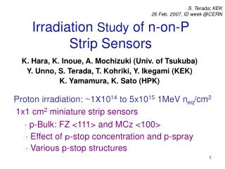
Simulations of Hadron Irradiation Effects for Si Sensors Using Effective Bulk Damage Model A. Bhardwaj1, H. Neugebauer2, R. Dalal1, M. Moll2, Geetika1, K. Ranjan1, 1University of Delhi, India, 2CERN, PH-DT, Geneva
Contents of presentation • Some confusing terms • - Need for a coherent approach • What is VFD in hadron irradiated Si sensor ? • Donor removal and Acceptor removal as double junction • effect • Neutron vs Charged hadron irradiation effect • Some TCT simulation results Ranjeet, Delhi Uni. 24th RD-50 workshop
Some confusing terms Most of these terms are well understood by the experts ! But can be really confusing and sometime misleading to the starting students! Effective doping density (Neff) - Hadron irradiation generates both acceptor and donor traps - Ionization of traps is strongly dependent on electric fields and concentration of electron and hole - More ionized acceptor near n+ and more ionized donor near p+ - Type inversion ? (…getting red TCT signals from both sides! A systematic study by Hannes, 23rd RD-50) - What is full depletion voltage for hadron irradiated sensors ? Donor Removal & Acceptor Removal - Are donors are actually removed from the Si bulk with hadronfluence ? - Or they are the parameterization terms used to represent the initial VFD drop with fluence ? Need for a coherent approach - May be choose more appropriate terms! - Realistic approach in terms of traps can be helpful in understanding complex issues
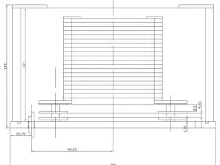
Simulation Model • Simulation structure • 1x1x300µm • Bulk type = n and p type • (each with three bulk doping 2e11 cm-3, 2e12cm-3 and 4e12cm-3) • Trap model • Simple two trap model for proton irradiation • Give correct leakage current • Give VFD550V at 253K for proton fluence = 1e15neq/cm2 Bulk model used for VFD simulations Ranjeet, Delhi Uni. 24th RD-50 workshop
VFD simulations for n-type Si • Initial VFD drop for all of the three bulk • doping • VFD minimum for bulk doping 2e11cm-3 • happen at very low fluence but for higher • bulk doping, VFD minimum is at higher • fluence • One is tempted to attribute this effect as • “Donor Removal” but we have not used • any donor removal in the simulations ! • The initial lowering of VFD is simply due to • the double junction effect in irradiated Si • Due to the double junction effect, depletion • of charge carriers starts from both sides of Si diode • Due to depletion from the both ends, Si diodes is depleted at lower VFD bias , for • initial fluences. • There may not be any need for the “Donor Removal” Ranjeet, Delhi Uni. 24th RD-50 workshop
Electric field evolution for n-type Si n-type bulk (4e12cm-3) Fluence = 5e14neq/cm2 n-type bulk (2e11cm-3) Fluence = 5e14neq/cm2 P+ n+ P+ n+ • Electric field start to grow from both sides • VFD is the bias at which electric fields from both sides meet each other (in fact VFD is • 20-30V higher then this bias) • Effect of initial bulk doping remain there but at higher fluences, space charges due • to traps are much more important Ranjeet, Delhi Uni. 24th RD-50 workshop
Current evolution for n-type Si n-type bulk (2e11cm-3) n-type bulk (4e12cm-3) - Current increases with bias and saturates around VFD - Consistent picture for VFD by 1/C2 plots, electric field plots and IV plots Ranjeet, Delhi Uni. 24th RD-50 workshop
VFD simulations for p-type Si • Initial VFD drop for all of the three bulk • doping • Very similar VFD for higher fluences • This effect is attributed to “Acceptor • Removal” • - Due to the double junction effect, depletion • of charge carriers starts from both sides of Si diode • Due to depletion from the both ends, Si diodes is depleted at lower VFD bias , for • initial fluences. • There may not be any need for the “Acceptor Removal” • (A very nice study about acceptor removal in23rd RD-50 CERN, by Kramberger) • But, • Why much more VFD lowering (or Acceptor removal) with proton irradiated sensors • (compare to neutron one) • Why more VFD lowering for MCz (Higher Oxygen) compare to Fz
Difference between neutron and charged hadron irradiation • Charged hadrons introduces much more E(30K) donors with energy level (EC - 0.1) eV • (NIM A 611 (2009) 52–68) • Introduction rate of E (30K) is 6x10⁻²cm-1 for proton irradiation, which is more then 6 • times the introduction rate for neutrons irradiation ( 9x10⁻³cm-1) • E (30K) is positively charged (almost always) during sensor operation • More E (30K) traps are generated in Oxygen rich samples (Roxana Radu, 24th RD-50) Much more negative space charge for Neutron irradiated sensors (very less amount of active donors, Higher VFD) More symmetric space charge distribution for pion irradiation (Stronger double junction effect, lower VFD) Neutron irradiated n+-p sensor n+ n+ p+ p+ Ranjeet, Delhi Uni. 24th RD-50 workshop
Effects of E (30K) trap on VFD • Additional positive space charge for charged hadron irradiated sensors • - More symmetric double junction electric fields (lower VFD) • For p-type sensors, stronger double junction effect for charged hadron irradiation • Lowering of VFD for initial fluences of charged hadrons • For p-type sensors lowering of VFD may appears as “Acceptor Removal” • VFD lowering will depend on Oxygen concentration of Si sensor • (As more E (30K) levels are introduced in Oxygen rich samples) • - Much steeper slop for VFD for neutron irradiated sensors • For n-type (p+-n) sensor (Donor type initial bulk doing), initial VFD lowering will happen for both neutron and charged hadrons • Appears as “Donor removal” • Oxygen concentration will affect the VFD slop • After initial dip in VFD, there will be steeper slop for VFD for neutron irradiated • sensors Ranjeet, Delhi Uni. 24th RD-50 workshop
Some TCT simulations Ranjeet, Delhi Uni. 24th RD-50 workshop
Mix mode simulation circuit Circuit used In KIT and UHH Circuit used for TCT simulations at DU • Since simulated diode structure is 120µm X 1µm X 300µm only • Cstray represent this extra capacitance and capacitance of cables or other electric components • Lstray is stray inductance of cables, electrical circuits • All other variables are more or less known with some confidence. • No preamp in circuit (Can affect TCT signal) Ranjeet, Delhi Uni. 24th RD-50 workshop
TCT : Measurement vs Simulation TCT signal for MCz n-in-n for front side illumination with Red laser (Fluence = 6.4e13neq/cm2) • TCT signals appeared only after reverse bias > 200V • (measurements at CERN, Micron diode) • Good agreement between simulated and measured TCT trends • Three trap model used (third trap, acceptor, Ec-0.45eV, e= h=1x10-16cm-2, Intro=40 Ranjeet, Delhi Uni. 24th RD-50 workshop
TCT : Measurement vs Simulation (Fluence = 1e15neq/cm2 protons) 500V • - Simulation trends looks similar to measurements (at UHH) • - Double junction is clearly visible (say at 500V) • Measured signal start at 0.5ns but simulation start at 2ns (which of course can be • shifted) • Three level trap model is used in TCT simulations
Summary/future outlooks • Some familiar terms used to quantify radiation damage may lead to confusion • - Need to follow the consistent approach based on traps • - Can be helpful in avoiding confusion • Due to the double junction effect, depletion of charge carriers may starts from both • ends of Si diode, thus, lowering the VFD • The VFD lowering for initial fluences, in n-type of sensors, may appear as “Donor • Removal” • The VFD lowering for proton irradiated p-type sensors may be due to double • junction effect • The higher E (30K) donor trap may be a reason for more symmetric electric field for • charged hadron and thus, higher apparent “Acceptor Removal” • E (30K) trap may be behind higher VFD for neutron irradiated sensors and better • properties of oxygenated Si • - Need more investigation • TCT simulations & measurements for irradiated sensors can provide information • about electric field inside the sensors • - More results in future meetings! Ranjeet, Delhi Uni. 24th RD-50 workshop
Thanks for your attention! Ranjeet, Delhi Uni. 24th RD-50 workshop
Back up ! Ranjeet, Delhi Uni. 24th RD-50 workshop