Download
1 / 43
430 likes | 569 Views
First Proton Irradiation of CMS Sensors. W. de Boer, A. Dierlamm, A. Furgeri, E. Grigoriev, F. Hartmann, F. Hauler, L. Jungermann, Ch. Piasecki. Some facts to remember for the next slides. Data is preliminary

E N D
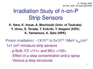
First Proton Irradiation of CMS Sensors W. de Boer, A. Dierlamm, A. Furgeri, E. Grigoriev, F. Hartmann, F. Hauler, L. Jungermann, Ch. Piasecki
Some facts to remember for the next slides • Data is preliminary • Measurements and evaluation was done in 4 days only including the weekend some plots can be arranged in a better way and the data is incomplete! (sorry!!!) • The biasing was done with conductive rubber residuals on AC pads sometimes gives contact problems • We used the testing of the teststructures to train personal • After irrad.: Strip scan for ST at Vbias=900V (it was stable) • The evaluation is not complete!
Materials • Hamamatsu Full Sensor (W6b 4919-39)Thickness: 500 mmResistivity: 4.6 kWcm • Hamamatsu teststructures (same batch no. 35-41) • Have to look up all other parameters accordingto the HPK tables • ST Full Sensor (04439218)Thickness: 500 mmResistivity: 5.1 kWcm
Simulated LHC conditions with respect to surface damage! Vbias
High fluence (2.5x10^14 neq/cm2) • FS Ham.@ 1V (AC & bias) • TS H39 @ 1V • TS H38 @ 12V • TS H37 @ 100V • TS H35 & H36 @ 0V • TS H40 @ 100V (only bias) 33MeV
Low fluence (1,5x10^14 neq/cm2) • FS ST @ 1V • TS ST26 @ 1V • TS H41 @ 0V
Fluence estimate (preliminary) Hamamatsu: • Leakage current on TS H39 diode at -8±1°C:I(-8°C) = 5 mA • Leakage current at 20°C (I(T)=I0*T1.5 *e-1.2eV/kT): I(20°C)= (860 ± 190)mA • Volume of diode is 72 mm3 => I(20°C)/V =(11.9 ± 2.6)mA/cm3 => Fluence is about (3.0±0.6)e14 neq/cm2(a=4e-17A/cm) ST: • Leakage current on TS H41I(-9°C) = 1.5 mA • Fluence is about (1.1±0.3)e14 neq/cm2
Leakage Current on Ham. Diode after Irrad. with high Fluence
Leakage Current on Ham. Diode after Irradiation with low Fluence
Leakage Current ST FS after irrad. 1-4nA before irrad.
Other Paramters on ST Sensor • Interstrip Capacitance (one neighbour):Before Irradiation 3.5 pFAfter Irradiation 3.6 pF • Interstrip Resistance:Before Irradiation > 10GW • No definite numbers after irrad
Poly Resistance on Ham. Sensor after Irradiation 300V, -13°C 160V
Interstrip Capacitance (one neighbour) vs. Bias Voltage after Irradiation
Interstrip Capacitance on TS after Irradiation (2 neighbours) Some bad contacts due to residuals of conductive rubber!?!?!
Interstrip Resistance on TS after Irradiation (very preliminary)
Conclusion: Procedure for the production • Evaluation on minisensor and FS only • Irradiation with protons is feasible with small bias voltage near to final LHC condition • We have to evaluate the irrad. sensor with higher Vbias • The IQC in Karlsuhe is ready with some possible improvements, learned at this system test level • Some additonal measurments and x-ray studies are ongoing and helpfull for the surface damage understanding but are not essential for the approval of an ingot!
CMS-GCD-Structures Diode Gate Diode Diode Gate Diode Diode Diode
Measurement of the CMS square GCD structure and Rose structure in literature KA Some non-understood points. Rose
GCD Summary • Proton irradiation has shown that bulk leakage current is much higher than interface currents at least at full dose and is therefore negligible. (see also NIM A444 (2000) 605-613)What about effects of type inversion? • However further studies at Karlsruhe are possible by using the KA X-Ray source.