Download
1 / 12
120 likes | 314 Views
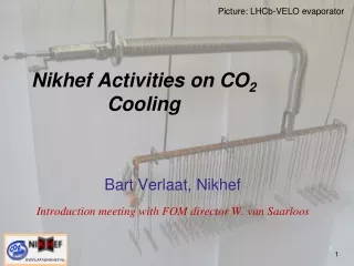
CO2 cooling at Nikhef. Auke Colijn for the Nikhef CO2 team. Warm cooling Cold cooling Titanium welding. Warm Cooler – Version: LHCb pump. TT104. PT104. CO2 return. H 2 O in. bypass. CO2 out. CO2 bottle. H 2 O out. FT101. TT101. TT103. PT101. PT103.

E N D
CO2 cooling at Nikhef AukeColijn for the Nikhef CO2 team Warm cooling Cold cooling Titanium welding
Warm Cooler – Version: LHCb pump TT104 PT104 CO2 return H2O in bypass CO2 out CO2 bottle H2O out FT101 TT101 TT103 PT101 PT103 1. LHCb spare membrane pump. 2. Waiting for CO2 proof version of gear pump (soon)
Warm Cooler: Measurement Setup • IBL like cooling tube • Tube with inlet and return capillary and sizes suitable for IBL • steel tube OD=2.0 mm, ID=1.6 mm • Heat over a length of 67 cm. Resistive heating • Temperature sensors • 8 on heated surface of tube • 1 before and 1 after • Pressure sensors • 1 before heated area • 1 after heated area • To measure saturation temperature TT201 TT202 TT203 TT204 TT205 TT206 TT207 TT208 TT209 TT210 TT211 PT201 PT202 Manifold Inlet 0.5mm Outlet 2mm CERN Stave WG Sept 1st 09 Joint From danilo’s talk
Warm Cooler: Running - PVSS Monitor of Plant & Experiment CO2 flow: by-pass open CO2 flow: by-pass closed Fill plant Pump with by-pass closed PowerScan: 0-220W / 22 steps PowerScan: 0-220W / 22 steps ΔT≈10C from pump inlet - outlet Dry-out
Cooling cycle: Mollier graph (PVSS logging + REFPROP) F CO2 return E H2O in bypass D C CO2 out H2O out B C CO2 bottle FT101 A B A D E
Temperature versus Power Density: flow 1.6g/sec Exceed critical heat flux Dry-out at x=0.6
Temperature versus Position on Tube: flow 1.6g/sec X=0.6 Saturation: 24.6C Sub-cooled liquid
IR pictures of stainless tube • Stainless SteelTube (same as before without sensors but painted black) • OD=2mm • ID=1.6mm • Length=0.8m • Outside painted black • Placed on styrofoam: at room temperature • On IR pictures • Last 0.2m of the tube • Power cable • Thermocouple connected with cable-ties • Swagelok tube connectors thermocouple connectors 0.2m Power cable
IR pictures: flow=1.5g/s; p=61bar; T saturation=24.5°C 0W 50W 100W 130W 145W 150W 160W 180W 210W
Dry-out on video (will put on youtube) • P=144W. Slight dry-out • P=200W. Much dry-out • P back to 144W. Return of 2-phase cooling (with bit of dry-out) • P=100W. Tube becomes ‘invisible’, because it is close to ambient temperature • P=0W. Sub-cooled CO2 throughout whole tube
Titanium Welding • Titanium grade 2 • Tube OD 3.2mm • Tube wall 0.5mm The good , the bad and the ugly • Swagelok orbital welder M100 • Protective gas: Ar (99.997%) Top-view welding fixture • We experiment with thinning tube walls before welding
Outlook • Make cold-cooler work in our lab • Use gear-pumps: no-oscillations, good for R&D • Measurements with IBL carbon stave – first objective with cold plant • Qualify titanium welding • Investigate Ti-SS vacuum brazing …..