Download
1 / 18
180 likes | 295 Views
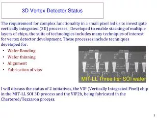
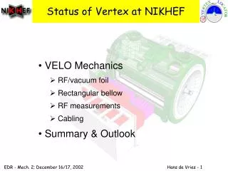
Status of Vertex at NIKHEF. VELO Mechanics RF/vacuum foil Rectangular bellow RF measurements Cabling Summary & Outlook. VELO Overview. Secondary vacuum box. Material data. Material: AlMg3 Young's modulus: 70.000 MPa Poisons ratio: 0.33 Shear Modulus: 27.3 GPa

E N D
Status of Vertex at NIKHEF • VELO Mechanics • RF/vacuum foil • Rectangular bellow • RF measurements • Cabling • Summary & Outlook
Material data Material: AlMg3 Young's modulus: 70.000 MPa Poisons ratio: 0.33 Shear Modulus: 27.3 GPa Yield Strength: 80-180 MPa Ultimate Strength: 180-260 MPa Electrical conductivity: 1.9x10⁷ ohm-1 m-1 (almost 50% of pure Al) Weldable!
Full size foil Vacuum tight foil from 300 µm AlMg3 Buckling in the center toblerones is solved Ribs (2.5mm high) are added at the forward-end to increase the stiffness.
FEM analysis ACP 5080, AlMg4.5Mn (Alimex)
FEM analysis: input Input model for the FEM calculations
FEM analysis: results CONCLUSION: The max stress (91 MPa) is 33% below the Yield Strength (130 MPa), so still elastic and safe. A max displacement of 0.3 mm is no problem.
Rectangular Bellow Sagging problems Vacuum leaks in corners Parallel effort in edge-welding
RF pick-up (1) Foil thickness: 30 mm Al; Power level in the 50 ohm coaxial line: 10 Watts at 40MHz. The Si detector was 5 mm from the foil outside conductor of the coax. In this condition there was no influence on the noise background.
RF pick-up (2) Cut a hole in the foil and put the silicon strip just 5 mm in front of this hole. The power level in this coax line was still 10 watt at 40MHz. The fieldlevels from this radiator are much higher then we can obtain with the beam through the RF foil. The result was that we do not see influence on the working of the silicon in combination with the electronics of the test setup at NIKHEF in febr. 2002.
RF shielding Frans Kroes has produced a note on Attenuation of an EM field by AlMg4 screen of 0.2 mm Conclusion: Assuming a conductivity of 0.33 of pure Al: At 1 mm distance to the rf screen: 1.415 x 10⁻³ V/m
Conductivity • Pure Al = 37 x 106 Ohm-1 m-1 • Measured (accuracy 10%) conductivity of 1 m long 1 cm wide strips of AlMg3: • undeformed = 17 x 106 Ohm-1 m-1 • deformed = 11 x 106 Ohm-1 m-1 • 45% for undeformed • 30% for deformed material
Cabling • Cables inside vacuum: • Heat production • Signal shielding • Kapton with 3 Cu layers: • = 25 micron kapton outside layer • --- 17 micron Cu (foil) • = 75 micron kapton • --- 17 micron lines (100 micron width) • = 75 micron kapton • ---17 micron Cu (foil) • = 25 micron kapton outside layer
Outgassing (2) Poly-amide-imide coating: 1.5 m2 Kapton cables: 20 m2
Summary and outlook • Bellow • Still under development • RF measurements • 300 µm Al gives sufficient rf shielding • Side flaps not needed • Outgassing • poly-amide-imide • Kapton cables with 3 Cu layers