Download
1 / 17
170 likes | 343 Views
Electron Beam Deposition Into the KrF Laser Gas. F. Hegeler a ), M.C. Myers, M. Friedman, J.D. Sethian, S.B. Swanekamp b) , D.V. Rose c) , D.R. Welch c) , and M. Wolford d) Naval Research Laboratory Plasma Physics Division Washington, DC 20375.

E N D
Electron Beam Deposition Into the KrF Laser Gas F. Hegelera), M.C. Myers, M. Friedman, J.D. Sethian, S.B. Swanekampb), D.V. Rosec), D.R. Welchc), and M. Wolfordd) Naval Research Laboratory Plasma Physics Division Washington, DC 20375 a) Commonwealth Technology, Inc., Alexandria, VA 22315 b)TITAN/JAYCOR, McLean, VA 22102 c)Mission Research Corporation, Albuquerque, NM 87110 d) SAIC, McLean, VA 22102 Work supported by the U.S. Department of Energy High Average Power Laser Program Workshop, Naval Research Laboratory, December 5, 2002
Summary • Should be able to meet ultimate goal of 80% e-beam energy deposition efficiency during the flat-top portion of the pulse at 750 kV. • Experimental measurements, plus 1-D and 3-D simulations that have been benchmarked with experiments, point the way: • No anode foil is needed (Demonstrated) • Pattern and counter-rotate e-beam to “miss” ribs (Demonstrated) • Reduce pressure foil from 2 mil to 1 mil (Demonstrated) • Shallower hibachi ribs (To be evaluated with new hibachi • in early Spring 2003) • 750 keV beam (as in ultimate application) • Eliminated electron beam halo with floating electric field shapers.
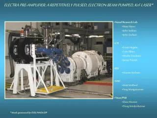
First Generation system can run at 5 Hz for 5 hoursExcellent test bed for developing laser components The Electra Laser Facility Two beams: 30 cm x 100 cm, 500 keV, 90 kA, 100 nsec @ 5 Hz
Amplifier Window The key components of a Krypton Fluoride (KrF) Laser Laser Input Laser Gas Recirculator Pulsed Power System Cathode Electron Beam Foil Support(Hibachi) Laser Cell (Kr + F2) ENERGY + (Kr + F2) (KrF)* + F (Kr + F2) + h (248 nm)
Opposite electron beams pump the laser cell Top view 120 cm 30 cm 1.8 m Cathode Hibachi Side view Hibachi
Diode Energy Distribution of a 6.1 kJ Pulse risetime 0.7 kJ fall time 1.2 kJ 100 ns flat-top 4.2 kJ Voltage and current waveforms from a single diode.
Laser Gas Kr + Ar Pressure Foil .001”Ti Vacuum e-beam Emitter Rib Goal: Maximize e-beam energy deposition in the laser cell (> 80% at 750 kV during the flat-top) Two innovations have allowed high hibachi transmission:1. Eliminate the anode foil2. Pattern the electron beam to “miss” the hibachi ribs Anode foil • Issues • High Current “edge” from each strip • Non-uniform electric field at anode causes beam spreading • Beam rotates and skews between cathode and anode
100 90 80 70 60 50 40 30 20 10 0 e-beam hits hibachi ribs Non-uniform foil heat loading. % beam energy deposited in gas 0 0.5 1.0 1.5 2.0 2.5 3.0 3.5 4.0 cathode strip width 3-D LSP simulation show that an anode foil can be eliminated E-beam beam spreading in the non-uniform electric field is controlled by the cathode strip width. cathode field shaper ribs foil Simulations by D. Rose & D. Welch MRC Albuquerque
Emitter Floating Field Shaper Floating “Field Shapers” on perimeter of cathode strips eliminate enhanced edge emission A/cm2 WITHOUT WITH FIELD SHAPER Line out of Radiachromic film image of beam at anode F. Hegeler, et al., Physics of Plasmas, vol. 9, October 2002, pp. 4309-4315.
96 cm The emitter strips are counter-rotated so that the beam goes straight through the hibachi ribs Cathode strips rotated 6 degrees 27cm Position of the hibachi ribs Radiachromic Film: Time integrated current profile at the pressure foil
Strip cathode increases energy deposition by 26% over monolithic cathode; performance close to “rib-less” hibachi Solid cathode, no ribs Emitter e-beam Pressure Foil Solid cathode, with ribs Ribs Strip cathode, with ribs Electron beam energy deposition efficiency at 500 kV, 1.2 atm. of Kr, and a 50 mm (2 mil) thick Ti pressure foil. Entire pulse Flat-top portion Simulation 67%72% (1-D Tiger) 93% of max Experiment 47%53% >26% Increase Experiment 62%67%
Diode voltage Flat-top efficiency with 50 mm thick Ti pressure foil Flat-top efficiency with 25 mm thick Ti pressure foil Flat-top energy deposition efficiency of up to 75% is achieved for 500 keV electrons, with a 1 mil Ti pressure foil 400 kV 57%(1) 71%(2) 500 kV 67%(3) 75%(4) Flat-top e-beam energy deposition efficiency with a strip cathode at 400-500 kV and 25-50 mm thick Ti pressure foils. Required laser cell gas pressure to “stop” the e-beam: (1) 1 atm. at 40% Kr and 60% Ar (2) 1 atm. at 60% Kr and 40% Ar (3) 1.2 atm. at 100% Kr (4) 1.3 atm. at 100% Kr
3-D LSP simulations and experimental measurementsagree well for the counter-rotated strip cathode E-beam deposition efficiency for the flat-top portion of the e-beam (500 kV) 80% with 2 mil Ti pressure foil 6 degree counter rotation 1.2 atm Kr in laser cell 2 mil Ti foil Simulations: 66% efficiency Experiments: 67% efficiency 70% 60% 50% deposited energy 40% 30% 20% 10% 0% laser gas pressure foil hibachi ribs Deposition efficiency = Energy deposited in laser gas/energy in diode (for flat top portion of beam) Simulations by D. Rose & D. Welch, MRC Albuquerque
3-D simulation of a single cathode strip and ribs confirms the 1-D results Static fields simulation with periodic boundaries in X; 2-cm wide cathode, 4-cm rib spacing, 30-cm of 1.2 atm Kr, 500 kV, 1 mil Ti foil. Foil Kr Gas Rib Number Density Periodic Boundary Energy deposition fractions: (for a 2-cm wide cathode) Gas: 76.6% Ribs: 12.6% Foil: 10.3% Other: <1%
New Hibachi with shallower ribs will increase the e-beam deposition efficiency • E-beam spreading is minimized • Electric field in A-K gap is more uniform compared to deep rib Hibachi 1 mil Ti pressure foil Hibachi ribs Preliminary simulation using new hibachi gives 74% energy deposition into gas at 430 kV.
1-D Tiger simulations at 750 kV 1-D codes predict a maximum energy deposition efficiency of 81% for a 750keV electron beam.