Simulink: MATLAB's Graphical Extension for Modeling and Simulation
Simulink is an interactive environment for modeling dynamic systems, offering block libraries for designing various systems like communications, controls, and signal processing. Learn how to create models, run simulations, and set parameters in Simulink.


Simulink: MATLAB's Graphical Extension for Modeling and Simulation
E N D
Presentation Transcript
SIMULINK - Graphical extension to MATLAB for modeling and simulation of systems
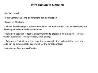
What is Simulink ? • Simulink is an environment for simulation and model-based design for dynamic and embedded systems. • It provides an interactive graphical environment and a customizable set of block libraries that let you design, simulate, implement, and test a variety of time-varying systems, including communications, controls, signal processing, and image processing.
Simulink offers… • A quick way of develop your model in contrast to text based-programming language such as e.g., C. • Simulink has integrated solvers. In text based-programming language such as e.g., C you need to write your own solver.
* In the MATLAB command window, at the >> prompt, type simulink and press Enter* Click on Simulink Library icon or How to Start...?
To open a new model General Simulink Libraries Block Sets Blocks
Opening a New Model Window • The first step in building a model is to open a new model window. • To do so, select Newfrom the File menu, and then select Model. This opens an empty model window, as shown in the following figure.
Simulink Library Browser • The Simulink Library Browser is the library where you find all the blocks you may use in Simulink. • Simulink software includes an extensive library of functions commonly used in modeling a system. • Continuous and discrete dynamics blocks, such as Integration, Transfer functions, Transport Delay, etc. • Math blocks, such as Sum, Product, Add, etc • Sources, such as Ramp, Random Generator, Step, etc
Sources • Source Blocks are used to generate signals • Notice that all of the source blocks have a single output and no input
Constant The Constant Source Block simply generates a constant signal • From File The From File Source Block outputs a signal taken from a specified .mat file. A matrix saved in MATLAB as a .mat file will become a signal • From Workspace Values are taken from workspace
Sinks • Sink Blocks are used to display or output signals. • Notice that all of the sink blocks have inputs and no outputs. Most have a single input.
Sinks • Scope – Used to display outputs as function of time • To File –The To File Sink Block saves a signal to a .mat file in the same way that the From File Source Block reads from a file • XY graph - The XY Graph Sink Block plots one signal against another. It is useful for phase-plane plots, etc. • To Workspace - The To Workspace Sink Block stores a signal in a specified workspace variable. Unlike the To File Sink Block, the time is not saved in the variable, and must be stored separately.
Moving Blocks into the Model Window • Click the + sign next to DSP system Block set in the left pane of the Library Browser. This displays a list of the Signal Processing Block set libraries. • Click Sources in the left pane. This displays a list of the DSP Sources library blocks in the right pane. If you do not see the Sine Wave block, scroll down the list until it is visible. • Click the Sine Wave block and drag it into the model window. • Click DSP Sinks in the left pane of the Library Browser. • Scroll down in the right pane of the Library Browser until you see the Vector Scope block, and drag the block into the model window to the right of the Sine Wave block
Connecting Blocks • The small arrowhead pointing outward from the right side of the Sine Wave block is an output port for the data the block generates. The arrowhead pointing inward on the Vector Scope block is an input port. To connect the two blocks, click the output port of the Sine Wave block and drag the mouse toward the input port of the Vector Scope block, as shown in the following figure.
Setting Block Parameters – Sine wave • Set Amplitude to 5. • Set Frequencyto 30. • Set Samples per frame to100. • ClickOK. Note: You mustset Samples per frame to a value larger than 1to see an image of the sinewave in the Scope block
Setting Simulation Parameters • Select the Simulation menu at the top of the model window. • Select Configuration parameters to open the Configuration Parameters dialog box, as shown in the following figure.
Setting Simulation Parameters • Here you set important parameters such as: • Start and Stop time for the simulation • What kind of Solver to be used (ode45, ode23 etc.) • Fixed-step/Variable-step • Solvers are numerical integration algorithms that compute the system dynamics over time using information contained in the model. • Simulink provides solvers to support the simulation of a broad range of systems, including continuous-time (analog), discrete-time (digital), hybrid (mixed-signal), and multi rate systems of any size.
Running the Model • Run the model by selecting Start from the Simulation menu. When you do so, • A scope window appears, displaying a sine wave.
Q:1 • In which library you can find sum of elements block Ans: Math operations
Q: 2 Following are steps to automatically connect blocks • Click and select the source block • Press and hold _____ key • Click and select the destination block Ans: Ctrl Key
Q:3 You can specify MATLAB workspace variables used as inputs and outputs to a Simulink model from which menu item A. File -> Model properties B. Simulation->Model configuration parameters->solver C. Simulation->Model configuration parameters->data import/export D. None of the above Ans: A,B,C
Example :1- Integrator • What type of solver can be used for integrator ? • Two give limits change in integrator block initial condition source in -> external • Replace constant with sine wave and see the result
Example :2- Integrator + Gain block • Try giving gain values as 3:1:10 • Saturation Values • Upper limit rand(8,1)*10 • Lower limit rand(8,1).*10
Ex:3 – Modeling Comparisons y = ((a>0) &&(b>0))||(c>0)
Ex:3 – Modeling Comparisons • What are the properties of random signal generator ? • What is the relation ship between sample period and pulse width?
Q:4 Which of the following blocks can be used to model the equivalent of a generic if-else statement • Logical operator • Switch • Relational operator • Demux Ans: Switch
Q:5 True or False: The logical operator block only provides the ability to perform the AND operation between two signals Ans: False
Ex 3:- Creating Subsystems • Scalability – Helps to reduce number of blocks • Readability • From Library browser • From existing blocks
Q:6 Which of the following is an advantage when using subsystems? • Helps reduce the number of blocks displayed in model window • Decreases simulation time • Facilitates grouping of functionally related blocks • Establishes hierarchy in model • Model requires less memory Ans: A,D
Q:7 The label of an input port on a subsystem matches the name of the corresponding inport blocks within subsystem Ans: False
Communication systems design Before starting to build the model, enter At the matlab command prompt • This sets the Simulink Boolean logic signals parameter to Off • Sets default simulation parameters that are optimal for models commstartup
Frames and Frame-Based Processing • A frame is a sequence of samples combined into a single vector. By setting Samples per frame to 100 in the Sine Wave block, you set the frame size to 100, so that each frame contains 100 samples. This enables the Vector Scope block to display enough data for a good picture of the sine wave.
Discrete Signals and Sample Times • The Sine Wave block in the Signal Processing Blocksetgenerates a discrete signal. • This means that it updates the signal at integer multiples of a fixed time interval, called the sample time. • You can set the length of this time interval in the Sample time parameter in the block's dialogue. • In the example described in Building a Simple Model, the Sample time has the default value of 1/1000. All the sources in the Communications Blockset and the Signal Processing Blocksetgenerate discrete signals exclusively. These sources are primarily designed for modeling digital communication systems.
Setting Simulation Parameters • If you typed commstartup before creating the model, the Stop time should be set to inf. • The Stop time determines the time at which the simulation ends. Setting Stop time to inf causes the simulation to run indefinitely, until you stop it by selecting Stop from the Simulation menu. • The Stop time is not the actual time it takes to run a simulation. • The actual run-time for a simulation depends on factors such as the model's complexity and your computer's clock speed. • The settings in the Configuration Parameters dialog box affect only the parameters of the current model.
Adding Noise to the Model • You can add noise to the model using the AWGN Channel block, from the Channels library of the Communications Blockset. • The block adds white Gaussian noise to the sine wave. Move the block from the Simulink Library Browser into the model window.
Double-click the AWGN Channel block to open its dialog • Then, click the down arrow in the Mode field and select Signal to noise ratio (SNR).