Simulink Basics
740 likes | 1.55k Views
Simulink Basics . Objectives. Describe Simulink environment List some of the commonly used signal sources available in Simulink to provide stimulus to a model List some of the commonly used sink blocks available in Simulink to view the output of a model

Simulink Basics
E N D
Presentation Transcript
Simulink Basics This material exempt per Department of Commerce license exception TSU
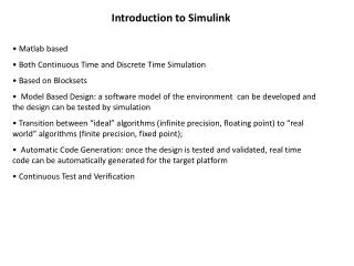
Objectives • Describe Simulink environment • List some of the commonly used signal sources available in Simulink to provide stimulus to a model • List some of the commonly used sink blocks available in Simulink to view the output of a model • State how hierarchical designs are created • Explain the sample period concept as implemented in Simulink After completing this module, you will be able to:
Outline • Introduction • Stimulus and Response • Sample Period • Solvers • Workspace • Design Hierarchy and Masked Subsystem • Summary
Simulink • The MathWorksSimulink environment: visual data flow environment for modeling and simulation of dynamical systems • Fully integrated with the MATLAB engine • Graphical block editor • Event-driven simulator • Models parallelism • Extensive library of parameterizable functions • Simulinkblockset: math, sinks, and sources • DSP blockset: filters or transforms, for example • Communications blockset: modulation or DPCM, for example
MATLAB and Simulink In this example, real-time frequency response from a microphone emphasizes the dynamic nature of the Simulink environment Response/Sink Stimulus/Sources
Outline • Introduction • Stimulus and Response • Sample Period • Solvers • Workspace • Design Hierarchy and Masked Subsystem • Summary
Sources in Simulink • Sources in Simulink are represented in double and provide stimulus • Some of the common sources used in DSP Design are • Band-limited White Noise – generates normally distributed random numbers • Chirp Signal – generates a sine wave whose frequency varies linearly over time • Constant • Free-running counter • From File – outputs data read from a MAT file • From Workspace – inputs data from the matlab workspace • Pulse Generator • Ramp • Sine Wave • Step
Sinks in Simulink • Sinks blocks are used to display instantaneous or aggregate values • Some common sink blocks used in DSP designs are • Display – shows the value of its input on its icon • Scope- displays its input with respect to time • To File – writes its input to a matrix in a MAT-file • To Workspace – writes data to the Matlab workspace • X-Y Graph – displays an X-Y plot of its inputs in a Matlab window
Using White Noise • A complement to the spectrum scope is the Gaussian White Noise block (Communications BlocksetComms sources) • This block outputs a signal over all frequencies below the Nyquist frequency • Useful for viewing filter cutoffs • Make sure you do not output vectors or frame-based data, because System Generator designs do not accept them Type WhiteNoise to view the example
Using the Scope • Click Properties to change the number ofaxes displayed and the Time range value(X-axis) • Use the Data History tab to control the number of values stored and displayed on the scope • Also, can direct output to workspace • Click Autoscale to let the toolsconfigure the display to the correct axisvalues quickly • Right-click the Y-axis to set its value
Using the Spectrum Scope • The spectrum scope is extremely useful for performing a frequency analysis on your design and can be found in the DSP blocksetDSP sinks library • Because no System Generator designs will use frame-based data, the input must be “buffered” (under the Scope properties). The size of the buffer determines the resolution of the FFT performed • Use overlapping to avoid the discontinuities of using finite data • Use the Axis properties to control the axes scale and units
Using the Spectrum Scope • This example takes two chirp signals (frequency-varying sine waves), adds them together, and views the results on the Spectrum Scope • Note: Be aware of the window that is being used by the scope, especially when analyzing small data sets. The default is hann Type ‘SpectrumScope’ to view the example
Combining Signals • To be viewed on a scope, multiple signals must first be combined • Use the MUX block (Simulink library Signals & Systems) to combine signals, thus making a vector out of them • Check FormatSignal Dimensionsand FormatWide NonScalar Linesto view the number of combined signals • Similarly, the DEMUX can be used to separate signals Type ‘vector’ to view the example
Outline • Introduction • Stimulus and Response • Sample Period • Solvers • Workspace • Design Hierarchy and Masked Subsystem • Summary
Sample Period • The units of the sample period can be thought of as arbitrary, but a lot of Simulink source blocks do have an essence of time • For example, a sample period of 1/44100 means that the function of the block will be executed every 1/44100 of a sec • Remember Nyquist’s theorem (Fs 2fmax) when setting sample periods • The sample period of a block directly relates to how that block will be clocked in the actual hardware. More on this later
Sample Period • Each block in a Simulink design has a “sample period,” and it corresponds to how often the function of that block is calculated and the results outputted • Every System Generator signal must be “sampled”; transitions occur at equidistant discrete points in time, called sample times • This sample period must be set explicitly for: • Gateway In • Blocks without inputs (Note: constants are idiosyncratic) • The sample period can be “derived” from the input sample times for other blocks
Outline • Introduction • Stimulus and Response • Sample Period • Solvers • Workspace • Design Hierarchy and Masked Subsystem • Summary
Solvers • The Simulink tool works by establishing a dialog between the system (the block diagram) and the solver (i.e., simulator) • The solver computes block outputs, then: • Updates discrete states (exact) • Decides on the next time step • The Simulink tool carries necessary information: • From system to solver: parameters and equations • From solver to system: computed states, inputs, and time • Set the solver options as: • Type: Fixed Step • Solver: Discrete (No Continuous States) • Tasking mod: Single Tasking Typical System Generator settings
Outline • Introduction • Stimulus and Response • Sample Period • Solvers • Workspace • Design Hierarchy and Masked Subsystem • Summary
Inputting Data From the Workspace • The “From Workspace” block can be used to input MATLAB data to a Simulink model • Format: • t = 0:time_step:final_time; • x = func(t); • Make these into a matrix for Simulink • Example: • In the MATLAB console, type: Type‘FromWorkspace’ to view the example • t = 0:0.01:1; • x = sin(2*pi*t); • simin = [t', x'];
Inputting Data From the Workspace • MATLAB expressions can be entered directly into the “From WorkSpace” block • Must be 2xn matrix • Column 1 = time values • Column 2 = data values • Often this is a more descriptive approach and does not require sourcing a MATLAB file prior to simulation Time values Data values
Outputting DataTo the Workspace • The “To Workspace” block can be used to output a signal to the MATLAB workspace • The output is written to the workspace when the simulation has finished or is paused • Data can be saved as a structure (including time) or as an array Type‘ToWorkspace’ to view the example
Outline • Introduction • Stimulus and Response • Sample Period • Solvers • Workspace • Design Hierarchy and Masked System • Summary
Creating Subsystems • All large designs will utilize hierarchy • Select the blocks that go into the subsystem. Click and drag to highlight a design region • Select Create Subsystem inthe Edit menu • Or press Ctrl+G • Use the modelbrowser under the View menu to navigate the hierarchy • Hierarchy in the VHDL code generated is determined by subsystems Type‘vector’ to view the example
Documenting a Design • Double-click the background to create a textbox • Type in the text • Right-click the text to change format • Left-click to move the textbox around • A masked subsystem can be given Help documentation. More on this later
Inports and Outports • Allow the transfer of signal values between a subsystemand a parent • Inport and Outport blocknames are reflected on thesubsystem • Can be found in Simulink Sinks (for the Outport)and SimulinkSources(for the Inport)
Masked Subsystems • The Simulink tool provides you with the power to personalize a subsystem—called masking • This enables you to: • Generate custom macro blocks with a custom icon • Create a parameter dialog box for the block • Create your help for the block • Shield complexity of the internals of the block • Protect the contents of a block from “dirty hands”
Masking a Subsystem • Right-click a subsystem and select Mask Subsystem (Ctrl+M) • The Mask editor contains the: • Icon editor • Parameters editor • Initialization editor • Documentation editor • To disable a mask, simply click unmask on the maskeditor
Icon Editor • The Icon tab controls the appearance of the icon • The Drawing Commands box allows you to use MATLAB syntax plotting and image commands to define your icon • Try: • plot(peaks) • disp(‘my Icon’) • image(imread(‘xilinx.jpg’)) • Experiment with the other properties to view their effects
Parameters Editor • The Parameters tab enables you to define and describe the mask dialog parameter prompts and name the variables associated with the parameters • You must: • Add a parameter • Give a prompt name • Assign a variable name to which to pass the value • Select the type of variable • Select whether to evaluate • Select whether it is tunable
Initialization Editor • TheInitialization tab allows you to specify initialization commands • After this, the MATLAB workspace variables are no longer visible • The Simulink tool executes the initialization commands when it: • Loads the model • Starts the simulation • Updates the block diagram • Rotates the masked block • Redraws icon of the block (if the icon of the creation code of the mask depends on the variables defined in the initialization code)
Documentation Editor • There are three fields: • Mask type • Mask description • Mask help (can be written in HTML). Click Help in the block mask to access the block help Type ‘maskedsubsytem’ to view the example
Outline • Introduction • Stimulus and Response • Sample Period • Solvers • Workspace • Design Hierarchy and Masked System • Summary
Knowledge Check • List at least three characteristics of Simulink • List at least four sources available in Simulink
Answers • List at least three characteristics of Simulink • Graphical block editor • Event-driven simulator • Models parallelism • Extensive library of parameterizable functions • List at least four sources available in Simulink • Sine wave • Constant • Ramp • From Workspace
Knowledge Check • List at least three sinks of Simulink • Spectrum scope is useful in performing a frequency analysis • True • False
Answers • List at least three sinks of Simulink • Scope • Spectrum scope • To Workspace • Spectrum scope is useful in performing a frequency analysis • True • False
Knowledge Check • What are the benefits of masked sub-systems?
Answers • What are the benefits of masked sub-systems? • Generate custom macro blocks with a custom icon • Create a parameter dialog box for the block • Create your help for the block • Shield complexity of the internals of the block • Protect the contents of a block from “dirty hands”
Summary • Simulink sources sinks deal with double data type • Simulink provides a concurrency which is essential to model real harwdare • Sources are used to provide stimulus to drive system • Sinks are used to observe response from system • Simulink supports hierarchical designs and using masked-subsystem one can protect those designs