Metal Working Processes
Metal Working Processes. Semester I Session 2013/2014. CLASSIFICATION OF MANUFACTURING PROCESSES. TOPIC OUTLINE. What is Sheet Metal ? Sheet Metalworking Processes Cutting processes Shearing Blanking Punching Forming processes Bending Roll forming Stretch forming Deep drawing


Metal Working Processes
E N D
Presentation Transcript
Metal Working Processes Bachelor of Industrial Technology Management with Honours Semester I Session 2013/2014
TOPIC OUTLINE • What is Sheet Metal? • Sheet Metalworking Processes • Cutting processes • Shearing • Blanking • Punching • Forming processes • Bending • Roll forming • Stretch forming • Deep drawing • Spinning • Equipment for Sheet Metal Working
LESSON OUTCOMES • Able to describe the characteristics and conditions of sheet metalworking processes. • Able to explain the main cutting and forming processes of sheet metal
METAL FORMING PROCESSES • Forming Processes are those processes in which material is plastically deformed to the desired shape and size • Characteristics of Forming Processes • Large capital expenditure for expensive equipment because of the large forces involved in heavy presses and dies • Suited for a large number of parts (high productionvolume) only • Production rate is fast • Advantage of near net-shape forming
WHAT IS SHEET METAL? • Sheet metal is simply metal formed into thin and flat pieces. • Between 0.006 and 0.25 inches thick • Thickness less than 6 mm (1/ 4 inches) - sheet • Thickness greater than 6 mm (1/ 4 inches) – plate • Available in a wide variety of materials, which include the following: • Aluminium - Brass - Bronze • Copper - Magnesium - Nickel • Tin - Titanium - Zinc • Stainless Steel
SHEETMETAL WORKING HISTORY Sheet metal working / stamping / formingwas developed as a mass production technology for the production of bicycles around the 1890’s.
APPLICATIONS • Aircraft Bodies • Automobiles bodies • Utensils used for domestic purposes • Beverage cans • Construction • Furniture • Advantages: • Can form complex shapes • Many material options • High production rate • Low labour cost • Short lead time possible • Disadvantages: • Limited to constant part thickness • Part may require several operations and machines • Large amount of scrap
SHEET METALWORKING • Sheet metal can be cut, bent, stretched and moulded into a nearly any shape. • Sheet metalworking processes is categorised into 2: • Cutting Processes • The applied force causes the material to fail and separate, allowing the material to be cut or removed. • Can create holes and cut outs in any 2D geometric shape. • Forming Processes • The applied force causes the material to plastically deform, but not to fail. • Can bend the sheet numerous times to different angles or stretch the sheet to create complex contours.
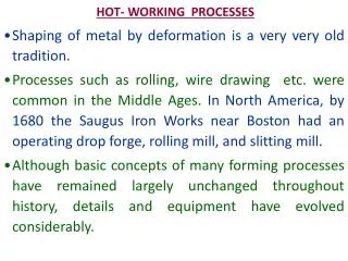
SHEET METAL FORMING PROCESSES Two conditions of sheet metal forming processes: • Hot working • Cold working Hot Working • Involves deformation at temperatures where recrystallisation can occur (0.6 - 0.8Tm). • Examples of hot working temperatures for each metal:
Hot Working Advantages • Higher ductility – more deformation without cracking. • Lower flow stress – less mechanical energy required for deformation. • Pores seal up. • Smaller grain size. • Stronger, tougher and more ductile than as-cast metals. Disadvantages • Surface reactions between the metal and the furnace atmosphere, i.e., oxidation (oxide scales). • Hot shortness, when the working temperature exceeds the melting temperature. • Dimension tolerance is poor due to thermal expansion at high temperatures. • Handling is more difficult (from furnace to machine).
Cold Working Normally performed at room temperature but in general < 0.3Tm, where recovery is limited and recrystallisation does not occur. Advantages • Provide work hardening, materials are stronger. • Provide fine grain size and good surface finish. • Dimension tolerance is better than in hot working. • Easier handling (low operating temperatures). Disadvantages • Use high amount of deformation due to low operating temperatures, therefore, require soft materials. • Equipment (rolls, dies, presses) is big and expensive. • Reduced ductility, therefore, require subsequent annealing treatments.
CUTTING PROCESS • Cutting processes are those in which a piece of sheet metal is separated by applying a great enough force to caused the material to fail. • When a great enough shearing force is applied, the shear stress in the material will exceed the ultimate shear strength and the material will fail and separate at the cut location. • Shearing force is applied by two tools (either a punch and die or upper and lower blades), one above and one below the sheet. • A small clearance is present between the edges of the upper and lower tools, which facilitates the fracture of the material. • Size of this clearance is typically 2-10% of the material thickness and depends upon several factors, such as the specific shearing process, material, and sheet thickness.
TYPES OF CUTTING PROCESS • Shearing • Produces straight line cuts to separate a piece of sheet metal. • Used to cut sheet stock into smaller sizes in preparation for other processes. • Performed on a shear machine, often called a squaring shear or power shear, that can be operated manually (by hand or foot) or by hydraulic, pneumatic or electric power. • The sheet is placed between the upper and lower blade, which are then forced together against the sheet, cutting the material. In most devices, the lower blade remains stationary while the upper blade is forced downward. • The upper blade is slightly offset from the lower blade, approximately 5-10% of the sheet thickness.
Shearing Shearing Machine
TYPES OF CUTTING PROCESS • Blanking • A piece of sheet metal is removed from a larger piece of stock by applying a great enough shearing force. • The piece removed, called the blank, is the desired part. • Used to cut out parts in almost any 2D shape, but is most commonly used to cut work pieces with simple geometries that will be further shaped in subsequent processes. • Often times multiple sheets are blanked in a single operation. • Final parts include gears, jewellery and watch or clock components. • Blanked parts typically require secondary finishing to smooth out burrs along the bottom edge.
Blanking • Hydraulic press drives the punch downward at high speed into the sheet. A small clearance, typically 10-20% of the material thickness, exists between the punch and die. • Sheet metal stock is placed over the die in the blanking press. The die,, has a cut out in the shape of the desired part and must be custom made unless a standard shape is being formed • When the punch impacts the sheet, the metal in this clearance quickly bends and then fractures. • This process is extremely fast, with some blanking presses capable of performing over 1000 strokes per minute.
TYPES OF CUTTING PROCESS • Punching • Material is removed from a piece of sheet metal by applying a great enough shearing force. • Very similar to blanking except that the removed material, called the slug, is scrap and leaves behind the desired internal feature in the sheet, such as a hole or slot. • Used to produce holes and cut outs of various shapes (circle, square, rectangle, etc.) and sizes. • The edges of these punched features will have some burrs from being sheared and secondary finishing operations are typically performed to attain smoother edges.
Punching • Requires a punch press, sheet metal stock, punch, and die. Sheet metal stock is positioned between the punch and die inside the punch press. The die, located underneath the sheet, has a cut out in the shape of the desired feature. • The punch press drives the punch downward at high speed through the sheet and into the die below. The slug that is punched out of the sheet falls freely through the tapered opening in the die. • A CNC punch press can be hydraulically, pneumatically, or electrically powered and deliver around 600 punches/ minute.
Punching A variety of operations are possible to form different features which include the following: • Piercing - The typical punching operation, in which a cylindrical punch pierces a hole into the sheet. • Slotting - A punching operation that forms rectangular holes in the sheet. • Perforating - Punching a close arrangement of a large number of holes in a single operation. • Notching - Punching the edge of a sheet, forming a notch in the shape of a portion of the punch. • Nibbling - Punching a series of small overlapping slits or holes along a path to cut out a larger contoured shape. • Lancing - Creating a partial cut in the sheet, so that no material is removed. The material is left attached to be bent and form a shape, such as a tab etc.
Punching • Slitting- Cutting straight lines in the sheet. No scrap material is produced. • Parting - Separating a part from the remaining sheet, by punching away the material between parts. • Cut off - Separating a part from the remaining sheet, without producing any scrap. • Trimming - Punching away excess material from the perimeter of a part, such as trimming the flange from a drawn cup. • Shaving - Shearing away minimal material from the edges of a feature or part, using a small die clearance. Used to improve accuracy or finish.
Manufacturing Technology (BPT 4413) FORMING PROCESS • Bending • A force is applied to a piece of sheet metal, causing it to bend at an angle and form the desired • Involves deformation in one axis only but a sequence of several different operations can be performed to create a complex part. • There is little change to the material surface area.
Manufacturing Technology (BPT 4413) • Performed on a machine called a press brake, which can be manually or automatically operated. • It contains an upper tool called the punch and a lower tool called the die, between which the sheet metal is located. • The sheet is carefully positioned over the die and held in place by the back gauge while the punch lowers and forces the sheet to bend. • By: • Suziyana Mat Dahan
Manufacturing Technology (BPT 4413) • Two types: • V-bending • Punch and die are "V" shaped. The punch pushes the sheet into the "V" shaped groove in the V-die, causing it to bend. • V-groove must have a sharper angle than the angle being formed in the sheet to allow for more control over the angle because there is less spring back. • By: • Suziyana Mat Dahan
Manufacturing Technology (BPT 4413) • Wipe/edge bending • Requires the sheet to be held against the wipe die by a pressure pad. • The punch then presses against the edge of the sheet that extends beyond the die and pad. The sheet will bend against the radius of the edge of the wipe die. • By: • Suziyana Mat Dahan
Manufacturing Technology (BPT 4413) • Spring back • The residual stresses in the material will cause the sheet to spring back slightly (elastic recovery) after the bending operation. • By: • Suziyana Mat Dahan
Manufacturing Technology (BPT 4413) • Methods to compensate: • Over bending - the punch angle and radius are smaller than the final ones. The final bend radius will be greater than initially formed and the final bend angle will be smaller. • Bottoming- squeezing the part at the end of the stroke. The punch forces the sheet to the bottom of the die cavity, called "bottoming". • By: • Suziyana Mat Dahan
Manufacturing Technology (BPT 4413) • Roll forming • Sheet metal is progressively shaped through a series of bending operations. • Performed on a roll forming line in which the sheet metal stock is fed through a series of roll stations. • Each station has a roller die, positioned on both sides of the sheet. The shape and size of the roller die may be unique to that station, or several identical roller dies may be used in different positions. • As the sheet is forced through the roller dies in each roll station, it plastically deforms and bends. • Roller dies are lubricated to: • Reduce friction between the die and the sheet • Allow for a higher production rate • Can be used to form a sheet into a wide variety of cross-section profiles. • Create very long sheet metal parts with various cross-section along its length, typical widths of 1-20 inches and thicknesses of 0.004-0.125 inches. • By: • Suziyana Mat Dahan
Manufacturing Technology (BPT 4413) • By: • Suziyana Mat Dahan
Manufacturing Technology (BPT 4413) • Stretch forming • A process in which a piece of sheet metal is stretched and bent simultaneously over a die in order to form large contoured parts. • Performed on a stretch press, in which a piece of sheet metal is securely gripped along its edges by gripping jaws. The gripping jaws are each attached to a carriage that is pulled by pneumatic or hydraulic force to stretch the sheet. • 2 methods: • Vertical stretch presses- form die rests on a press table that can be raised into the sheet by a hydraulic ram. As the form die is driven into the sheet, which is gripped tightly at its edges, the tensile forces increase and the sheet plastically deforms into a new shape. • Horizontal stretch presses - mount the form die sideways on a stationary press table, while the gripping jaws pull the sheet horizontally around the form die. • Formed parts are typically large and possess large radius bends. • Shapes - vary from a simple curved surface to complex non-uniform cross sections. • Capable of shaping parts with very high accuracy and smooth surfaces. • By: • Suziyana Mat Dahan
Manufacturing Technology (BPT 4413) • Ductile materials – such as aluminum, steel, and titanium. • E.g. large curved panels such as door panels in cars or wing panels on aircraft. • By: • Suziyana Mat Dahan
Manufacturing Technology (BPT 4413) Manufacturing Technology (BPT 4413) 38 • By: • Suziyana Mat Dahan
Manufacturing Technology (BPT 4413) • Deep drawing • A process in which sheet metal is stretched into the desired part shape. • A tool pushes downward on the sheet metal, forcing it into a die cavity in the shape of the desired part. • Deep drawn parts are characterized by a depth equal to more than half of the diameter of the part. • Most effective with ductile metals, such as aluminium, brass, copper, and mild steel to produce automotive bodies and fuel tanks, cans, cups, kitchen sinks, and pots and pans. • Requires a blank (sheet metal, typically a disc or rectangle), blank holder (to clamp down the blank over the die), punch (moves downward into the blank and draws, or stretches, the material into the die cavity), and die (has cavity). • Movement of the punch is usually hydraulically powered to apply enough force to the blank. • Both the die and punch experience wear from the forces applied to the sheet metal and are therefore made from tool steel or carbon steel. • After a part is completely drawn, the punch and blank holder can be raised and the part removed from the die. The portion of the sheet metal that was clamped under the blank holder may form a flange around the part that can be trimmed off. • By: • Suziyana Mat Dahan
Manufacturing Technology (BPT 4413) • By: • Suziyana Mat Dahan
Manufacturing Technology (BPT 4413) • Clearance – distance between the punch and the die and is about 10% greater than the stock thickness. • Holding force - improper application of the holding force can cause severe defects in the drawn parts such as: (a) Flange wrinkling (b) Wall wrinkling - holding force is too small (c) Tearing - holding force is overestimated • By: • Suziyana Mat Dahan
Manufacturing Technology (BPT 4413) • Spinning • Used to form cylindrical parts by rotating a piece of sheet metal while forces are applied to one side. • A sheet metal disc is rotated at high speeds on lathe (manual or CNC), while rollers press the sheet against a tool, called a mandrel, to form the shape of the desired part. • Spun metal parts have a rotationally symmetric, hollow shape, such as a cylinder, cone, or hemisphere to produce cookware, musical instruments etc. • Requires blank (disc-shaped piece of sheet metal), mandrel (a solid form of the internal shape of the part, against which the blank will be pressed- made from wood or plastic), and roller tool (made from steel or brass). • Mandrel and blank are clamped together and secured between the headstock and tailstock. • Force is applied to the sheet by a roller tool, causing the sheet to bend and form around the mandrel. • The tool may make several passes to complete the shaping of the sheet. • By: • Suziyana Mat Dahan
Manufacturing Technology (BPT 4413) • By: • Suziyana Mat Dahan
Manufacturing Technology (BPT 4413) • 2 methods: • Conventional spinning- roller tool pushes against the blank until it conforms to the contour of the mandrel. Spun part will have a diameter smaller than the blank, but will maintain a constant thickness. • Shear spinning- roller not only bends the blank against the mandrel, it also applies a downward force while it moves, stretching the material over the mandrel. Spun part outer diameter will remain equal to the original blank diameter, but the thickness of the part walls will be thinner. • By: • Suziyana Mat Dahan
Manufacturing Technology (BPT 4413) EQUIPMENT FOR SHEET METALWORKING • Basic equipment consists of mechanical, hydraulic, pneumatic or pneumatic-hydraulic presses with wide variety of designs, features, capacities and computer control. • By: • Suziyana Mat Dahan
Manufacturing Technology (BPT 4413) • Proper selection of such equipment is essential to achieve: • High production rate • Good dimensional control • High product quality • Efficient operation of the system • Equipment selection depends on several factors: • Type of forming operation, the size and shape of the dies, and the tooling required • Size and shape of the work piece • Maximum force required • Type of mechanical, hydraulic and computer controls • Features for changing dies • Safety features • By: • Suziyana Mat Dahan
Manufacturing Technology (BPT 4413) Thank You ! • By: • Suziyana Mat Dahan