Chapter 16 Oscillators
Chapter 16 Oscillators. Objectives. Describe the basic concept of an oscillator. Discuss the basic principles of operation of an oscillator. Analyze the operation of RC and LC feedback oscillators. Describe the operation of the basic relaxation oscillator circuits.

Chapter 16 Oscillators
E N D
Presentation Transcript
Objectives • Describe the basic concept of an oscillator • Discuss the basic principles of operation of an oscillator • Analyze the operation of RC and LC feedback oscillators • Describe the operation of the basic relaxation oscillator circuits • Discuss the use of a 555 timer in an oscillator circuit
Introduction Oscillators are circuits that produce a continuous signal of some type without the need of an input. These signals serve a variety of purposes. Communications systems, digital systems (including computers), and test equipment make use of oscillators.
The Oscillator An oscillator is a circuit that produces a repetitive signal from a dc voltage. The feedback oscillator relies on a positive feedback of the output to maintain the oscillations. The relaxation oscillator makes use of an RC timing circuit to generate a nonsinusoidal signal such as square wave.
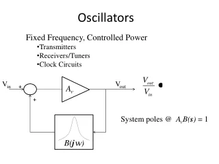
Feedback Oscillator Principles The feedback oscillator is widely used for generation of sine wave signals. The positive (in phase) feedback arrangement maintains the oscillations. The feedback gain must be kept to unity to keep the output from distorting.
Oscillators With RC Feedback Circuits RC feedback oscillators are generally limited to frequencies of 1 Mhz or less. The three types of RC oscillators we will discuss are the Wien-bridge, the phase-shift, and the twin-T.
Oscillators With RC Feedback Circuits The lead-lag circuit of a Wien-bridge oscillator reduces the input signal by 1/3 and yields a response curve as shown. The frequency of resonance can be determined by the formula below. fr = 1/2RC
Oscillators With RC Feedback Circuits The lead-lag circuit is in the positive feedback loop of Wien-bridge oscillator. The voltage divider limits gain. The lead lag circuit is basically a band-pass with a narrow bandwidth (high Q).
Oscillators With RC Feedback Circuits Since there is a loss of about 1/3 of the signal in the positive feedback loop, the voltage-divider ratio must be adjusted such that a positive feedback loop gain of 1 is produced. This requires a closed-loop gain of 3. The ratio of R1 and R2 can be set to achieve this.
Oscillators With RC Feedback Circuits To start the oscillations an initial gain greater than 1 must be achieved. The back-to-back zener diode arrangement is one way of achieving this. When dc is first applied the zeners appear as opens. This allows the slight amount of positive feedback from turn on noise to pass.
Oscillators With RC Feedback Circuits The lead-lag circuit narrows the feedback to allow just the desired frequency of these turn transients to pass. The higher gain allows reinforcement until the breakover voltage for the zeners is reached.
Oscillators With RC Feedback Circuits Automatic gain control is necessary to maintain a gain of exact unity. The zener arrangement for gain control is simple but produces distortion because of the nonlinearity of zener diodes. A JFET in the negative feedback loop can be used to precisely control the gain. After the initial startup and the output signal increases the JFET is biased such that the negative feedback keeps the gain at precisely 1.
Oscillators With RC Feedback Circuits The phase shift oscillator utilizes three RC circuits to provide 180º phase shift that when coupled with the 180º of the op-amp itself provides the necessary feedback to sustain oscillations. The gain must be at least 29 to maintain the oscillations. The frequency of resonance for the this type is similar to any RC circuit oscillator. fr = 1/26RC
Oscillators With RC Feedback Circuits The twin-T utilizes a band-stop arrangement of RC circuits to block all but the frequency of operation in the negative feedback loop. The only frequency allowed to effectively oscillate is the frequency of resonance.
Oscillators With LC Feedback Circuits For frequencies above 1 Mhz, LC feedback oscillators are used. We will discuss the Colpitts, Clapp, Hartley, Armstrong, and crystal-controlled oscillators. Transistors are used as the active device in these types.
Oscillators With LC Feedback Circuits The Colpitts oscillator utilizes a tank circuit (LC) in the feedback loop. The resonant frequency can be determined by the formula below. Since the input impedance affects the Q, an FET is a better choice for the active device. fr = 1/2LCT
Oscillators With LC Feedback Circuits The Clapp is similar to the Colpitts with exception to the additional capacitor in the tank circuit. The same formula applies as for the Colpitts.
Oscillators With LC Feedback Circuits The Hartley oscillator is similar to the Clapp and Colpitts. The tank circuit has two inductors and one capacitor. The calculation of the resonant frequency is the same.
Oscillators With LC Feedback Circuits The Armstrong uses transformer coupling in the feedback loop. For this reason the Armstrong is not as popular.
Oscillators With LC Feedback Circuits The crystal-controlled oscillator is the most stable and accurate of all oscillators. A crystal has a natural frequency of resonance. Quartz material can be cut or shaped to have a certain frequency. We can better understand the use of a crystal in the operation of an oscillator by viewing its electrical equivalent.
Oscillators With LC Feedback Circuits Since crystal has natural resonant frequencies of 20 Mhz or less, generation of higher frequencies is attained by operating the crystal in what is called the overtone mode. Overtones are usually odd multiples of a crystal’s fundamental.
Relaxation Oscillators Relaxation oscillators make use of an RC timing and a device that changes states to generate a periodic waveform. This triangular-wave oscillator makes use of a comparator and integrator to actually produce both a triangle wave and square wave.
Relaxation Oscillators Output levels are set by the ratio of R2 and R3 times the maximum output of the comparator. The frequency of output can be determined by the formula below. fr = 1/4R1C(R2/R3)
Relaxation Oscillators The voltage-controlled sawtooth oscillator’s frequencycan be changed by a variable dc control voltage. One possible type uses a programmable unijunction transistor.
Relaxation Oscillators The forward voltage of the PUT (VF) determines the frequency of the output. The formula below shows the relationship. f = VIN/RiC(1/Vp-VF)
Relaxation Oscillators A square wave relaxation oscillator uses the charging and discharging of the capacitor to cause the op-amp to switch states rapidly and produce a square wave. The RC time constant determines the frequency.
The 555 Timer As An Oscillator The 555 timer is an integrated circuit that can be used in many applications. We will discuss its operation as a square wave oscillator. The frequency of output is determined by the external components R1, R2, and C. The formula below shows the relationship. fr = 1.44/(R1 + 2R2)C Detailed operation is described within the text.
The 555 Timer As An Oscillator Duty cycles can be adjusted by values of R1 and R2. The duty cycle is limited to 50% with this arrangement. To have duty cycles less than 50%, a diode is placed across R2. The two formulas show the relationship. (see following slide) Duty Cycle >50 % = R1 + R2/R1 + 2R2 x 100% Duty Cycle <50 % w/diode = R1/R1 + R2 x 100%
The 555 Timer As An Oscillator The 555 timer by be operated as a VCO with a control voltage applied to the CONT input (pin 5).
Summary • Sinusoidal oscillators operate with positive feedback. • Two conditions for oscillation are 0º feedback phase shift and feedback loop gain of 1. • The initial startup requires the gain to be momentarily greater than 1. • RC oscillators include the Wien-bridge, phase shift, and twin-T. • LC oscillators include the Colpitts, Clapp, Hartley, Armstrong, and crystal.
Summary • The crystal actually uses a crystal as the LC tank circuit and is very stable and accurate. • A voltage controlled oscillator’s (VCO) frequency is controlled by a dc control voltage. • A 555 timer is a versatile integrated circuit that can be used as a square wave oscillator or pulse generator.