CSC Electronics
CSC Electronics. Radiation assurance P. O’Connor, BNL Y. Li, UCI Dec. 1, 2000. CSC Electronics. precision forward muon chambers 32 chambers at Z ~ 7m, R ~ 1 to 2 m electronics mounted on the chamber. On-chamber electronics location. CSC On-chamber electronics.

CSC Electronics
E N D
Presentation Transcript
CSC Electronics Radiation assurance P. O’Connor, BNL Y. Li, UCI Dec. 1, 2000
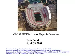
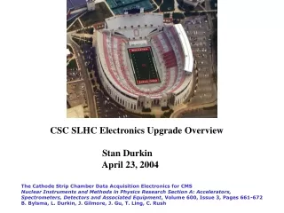
CSC Electronics • precision forward muon chambers • 32 chambers at Z ~ 7m, R ~ 1 to 2 m • electronics mounted on the chamber
CSC On-chamber electronics • Amplifiers, analog memory, digitizer, fiber optic links • 192-channel “ASM-PACK”
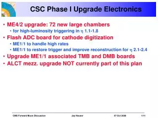
CSC Electronics reliability • Radiation qualification is part of overall reliability strategy • Goal: < 0.1% data lost due to hard or soft fails • Strategy: on-detector electronics boards must be as simple and robust as possible • ·Minimal parts list: see next slide • ·All intelligence to reside off-chamber (sparsifier/ROD) • ·ASM-PACK to have no • Configuration registers • Programmable logic • FIFOs • RAM • Counters • State machines • ·Thorough radiation test of all components • ·ESD protect inputs at board and chip level • ·ATLAS policy on grounding and shielding • ·Extra attention to amplifier stability • ·No DCS • Minimal monitoring
ASM-PACK components • Preamp/shaper – custom CMOS ASIC • SCA – custom DMILL ASIC* • Op-amp* • Voltage regulators* • 12-b ADC* • PECL translator* • G-link transceiver* • G-link serializer* • G-link deserializer • Multiplexer * These components common to LAr and CSC systems
Electronics qualification status • Majority of components are common with LAr • SRL’s are similar to LAr • Rad qualification of these components to be done jointly– already much progress from LAr groups • Preamp/shaper shows encouraging TID results to 1 Mrad (see next slide) • Other critical component is G-link receiver • SEE test set being constructed at UCI • Tests expected to start in Q1-2001 • Multiplexer – beginning to prototype with FPGAs, still have to choose rad-tolerant technology (discrete shift registers or ASIC)
Preamp/shaper 60Co irradiation results Supply current Gain Noise Waveform
Receiver qualification is critical for CSC readout scheme Acceptable SEU rate determined based on expected link sync loss behavior Proton facility at UC Davis identified All hardware designed, fabricated, and partially debugged All software (Labview) written Optical components ready 2 long and 3 short cables being assembled Optical link qualification