Download
1 / 24
240 likes | 441 Views
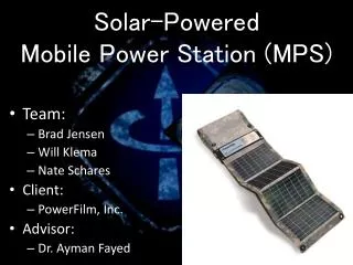
Mobile Power Station (Phase 2). Team: May 12-03 Team member : Avinav Verma , Dixiao Jiang, MengQian Ding Advisor: Aymen Fayed Client : Powerfilm . Inc. What’s mobile power station?. Li-ion Charging Cycle .

E N D
Mobile Power Station (Phase 2) • Team: May 12-03 • Team member: AvinavVerma, DixiaoJiang, MengQian Ding • Advisor: Aymen Fayed • Client : Powerfilm . Inc
Li-ion Charging Cycle Li-ion battery charging cycle includes three phases: trickle, constant current, and constant voltage. The charging cycles must be strictly followed to prevent battery pack overcharge and fire.
We would like to upgrade it to a more powerful processor that will have a higher operating frequency, more flash memory, and more integrated ADCs to enable sensing more signals in the system. • The other thing we need to consider is track the max point voltage accurately. The MPPT algorithm needs to be improved to avoid being stuck in local maxima. • Make high side current sensor more accurate • Send data to from microcontroller to computer so we can monitor charging state Functional requirement
Design Microprocessor According to the previous project, the MSP430f2013 MCU, which runs at 16MHz with 2kB of flash memory and 4 -16bit ADCs has good performance, however, we want a higher performance microprocessor in our project. The requirements of new microprocessor are: a. higher operating frequency b. more flash memory c. more integrated ADCs to enable sensing more signals
Microprocessor cont. Comparison between MCUs: Flash (KB) ADC ADC Channels Numeric Price Freq. (MHz)
MPPT algorithms dP - O&P algorithm (This year) • Whey we chose this method ? • It is a improved method of O&P method • It does not track wrong direction under rapid change in atmosphere
Buck converter To maximize efficiency we used the following equations to calculate ripple current and ripple voltage. = switching period Ripple Current: d = duty cycle Ripple Voltage:
High current sensor • The customer says: We were able to read currents obviously, but as some times we could be as far off as 100mA or more which is not very acceptable for a finished product…….We would like to get accuracy better than 10mA-50mA, this may require some tuning.
We think the problem is offset voltage of op amp. • Then we analysis the circuit including VOS of amp. • increase Rs can dramatically reduce current sensor error
Communication board • We want to send data from MSP430 Target board to computer, so we can reflect our microcontroller’s data on GUI. With this data, we can check our C code program and monitor our circuit. popular solution is to connect the UART of the MSP430 to a USB to UART converter such as the FT232RL and FT2232 from FTDICHIP.
Implementation/ Testing • PCB board
Code • Buck_Control and MPPT test
voidmppt(void) { solar_voltage1 = ADC(1); solar_current1 = ADC(2); pwm(0,1); //back 1/2 T solar_voltage2 = ADC(1); solar_current2 = ADC(2); pwm(1,2); //forward T solar_voltage3 = ADC(1); solar_current3 = ADC(2); power_0 = (long)solar_voltage1 * solar_current1; //current power power_1 = (long)solar_voltage2 * solar_current2; //previous 1/2T power power_2 = (long)solar_voltage3 * solar_current3; //forward 1/2T power dP = (long)2*power_0 - power_1-power_2; if(dP==0){ pwm(0,0); } else { if(dP>0){ if(solar_voltage3 > solar_voltage2){ pwm(1,2); //increase T's voltage } else{ pwm(0,2); //decrease T's voltage } } else{ //dP<0; if(solar_voltage3 > solar_voltage2){ pwm(0,2); //decrease T's voltage } else{ pwm(0,2); //increase T's voltage } } } } • /* • * buck_control.c • * • * Created on: 2012-2-9 • * Author: dxjiang • */ • #include "msp430f5172.h" • #include "PWM.h" • //char pwm_limit1=0; • voidbuck_control (unsignedint measurement, unsignedint desired){ • signedint delta = measurement - desired; • if(delta>0) pwm(0,2); //buck voltage too high; • elseif(delta<0) pwm(0,2); // buck voltage too low • //else pwm_limit1=0; buck voltage right on • __delay_cycles(10); //give buck converter time to settle • }
we can see data transmit from microcontroller to computer. However, after some good data, there is some garbage signal. We think that’s due to the noise of the MSP430. So we decide to close the pin after the data transmitted. If we want to transmit again, then reopen the pin. In this way, the noise is significant reduced.
Battery and Battery Monitor • To test the circuit, we use Tenergy high discharge Li polymer battery as the target battery to charge. We use TI bq20Z70 with EV2300 to monitor the battery charging.
Lessons learned • If you don’t have any idea on how to use a software, check Youtube. • Google the error, there always people have same problem as you. • Ask as many people as you can when you stuck somewhere. There are always someone can help you. • Make PCB board as early as possible
Future work • Make a interface that is easier to check the data send to computer • Using Li-Ion Phosphate battery instead of traditional Li-Ion • Figure out why EVM can’t send battery data to computer