Download

1 / 55
620 likes | 1.11k Views
Learn to interpret, model, and represent assemblies for product understanding. Explore functions, impacts, materials, and fastening techniques.

E N D
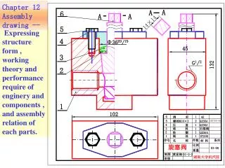
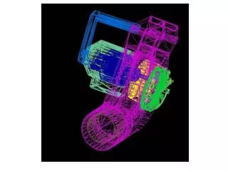
Assemblies “Interpretation of machine and flat pack assembly drawings is a necessary skill for many household and other common assemblies products, and these are seen as the primary source of material for study” “These skills are developed through the ability to interpret, model and represent multi view projections from a number of single components.” “Assemblies provide the ideal platform for 3D CAD Modelling.” Design & Communication Graphics Syllabus, Page 33 In order to graphically represent an assembled product, it is first necessary to investigate the product, and gain an appreciation for its individual parts, design and function.
Function Impact Materials Fastening Exploration of Assemblies • List the function(s) of the object • Identify what contribution each part makes to the overall function of the object • Investigate how the necessary contribution of each part impacts on its own design and the overall design of the object • Explore how the required function and hence design of each part determines the choice of material and surface finish • Explore how the need for accessibility to various individual parts of the object and design requirements determines the fastening techniques
Function Product investigation Applying this system to a common everyday object …… …..Door bell switch The primary function of the door bell switch is to complete an electrical circuit to cause a bell to sound A number of parts are required in order for the door bell switch to function successfully.
Function Outer Casing – Contribution to function • To protect the other parts from the elements • To enclose the parts with function and aesthetics in mind • The casing is not essential to the operation of the door bell switch; • With the casing removed the button can be used and the bulb stays lighting
Fastening Impact Materials Outer Casing – Materials & fastening The casing “clips” onto the mounting bracket in a “push to fit” arrangement allowing access to the workings inside. A wedge shape protrusion keeps the casing in place. The use of PTFE makes the casing durable and pleasing to the eye
Impact Materials Mounting Bracket – Contribution to function The flange on the switch mounting lines up with the collar on the mounting bracket to keep it in position The step at the base of the bracket allows the light from the bulb to illuminate the bell push; The translucent acrylic disperses the light effectively
Function Materials Fastening Mounting Bracket – Contribution to function • The mounting bracket has four main functions:- - securing the outer casing - locating the switch on the wall or door frame - houses the switch mounting - allows illumination of the door bell switch • Screws are used to fix the bracket in place - corrosion resistant coating
Sub Assembly – Switch Mounting The switch mounting is a sub-assembly within the main assembly. It houses a number of parts which when operated complete the circuit to sound the door bell
Material Impact Material Function Exploration of the button The button; • is made from PTFE • is cylindrical in shape and has filleted edges which make it smooth to the touch • houses a contact made from copper; which when brought in contact with the circuited contacts, sounds the bell
Function Material Material Further parts of the Door Bell switch • The circuited contacts are made from copper – good conductor • They are fastened in place using self tapping screws • A spring is placed in between the button and switch mounting. • Repeat operation of the bell push. • The spring is manufactured from high tensile steel.
Impact Fastening Further parts of the Door Bell switch • A step at the base of the slot in which the button contact moves when operated prevents the arrangement from coming apart
Further parts of the Door Bell switch • A bulb is inserted into a cylindrical hole and is powered by fastening its wires between the copper contacts and base of the switch housing • The door bell switch is powered by connecting AC power to the two contacts at the base of the switch mounting. The self tapping screws are loosened and the wires are looped around the shafts of the screws.
Product investigation – Door Bell Switch • By working through this process we gain an understanding for the products individual parts, design and function. • This understanding may be presented in digital images, freehand sketches, CAD models, notes and detail drawings.
Graphical representation – Detail Drawing • All necessary detailed information supplied to enable manufacture without reference to another source • Usually orthographic views • Ample space allowed around each drawing for notes and dimensions • Material and surface finish may be specified
Assembly Drawings • Shows all components assembled in functional position • Indicates how components fit together • Typically contains sectional views to add clarity • Dimensioning of assembly not necessary, unless requested - refer to detail drawings of components
Linetypes Type A – Continuous thick – Visible outlines & edges Type B – Continuous thin – Dimensions, projection and leader lines. Hatching Type C – Continuous thin irregular Type D –Continuous thin straight with zigzags Type E – Dashed thin – Hidden outlines & edges Type F – Chain thin – Centre lines, lines of symmetry Pitch lines and pitch circles Type G – Chain thin, thick at ends - Limits of partial or interrupted views - Cutting Planes and changes of direction
Scale 1:3 Scales • Scale of drawings are always quoted Enlarged Scale • All details generally drawn to the same scale. • If not the scale should be clearly noted on each detail drawing • Detail drawings of small components are sometimes drawn larger than actual size and larger details are drawn to a reduced size Scale 2:3
Third Angle Projection First Angle Projection Projection Systems • First or third angle projection are used in assembly drawings. • The projection symbol is used to indicate which form of projection is used. • Recommended proportions for projection symbol based on ‘D’
Plain Bush Terminology Housing – a component into which a “male” mating part fits Bush – a removable sleeve or simple bearing It may be plain cylindrical or flanged. The bush fits into the housing and may be easily replaced when worn. Boss – a cylindrical projection on the surface of a component Flanged Bush
Terminology • Chamfer – bevelled or sloping edge • Fillet – rounded portion or edge suppressing a sharp edge • Flat – a surface machined parallel to the shaft axis On a detail drawing, a flat surface is indicated with an X from corner to corner.
Key Hub Shaft Terminology • Key – a small block inserted between a shaft and hub to prevent the hub from spinning freely on the axle • Keyway – a slot or groove cut into a shaft into which the key is placed. • Note: A corresponding groove must be cut in the hub.
Terminology • Through hole – A hole which passes all the way through a part • Blind hole – a hole that passes only partially through a part • Countersunk hole – provides a seat for a countersunk screw or rivet • Counter-bore – provides a housing for the heads of cap screws or bolts • Tapped hole – A hole with an internal thread to accept a bolt or screw. Blind Hole Countersunk hole Counterbore hole Note: The countersunk or counterbore holes will ensure that the head of the screw is under, or flush with, the surface Through hole
Terminology • Rib/Web – a reinforcement positioned to support or stiffen adjacent parts • Spokes – a rod or bar, projecting radially from the hub of a wheel, supporting the rim
Terminology - Fasteners Round Head Screw – used where an aesthetic finish is required. Countersunk Screw – used when the screw head must be flush with the surface. Socket Head Screw – Cylindrical head with a hexagonal recessed drive. Counterbored holes allow the head to be flush with the surface.
Plain Terminology - Fasteners Grub-screw – used to prevent relative motion between parts eg. A pulley and shaft Nut – Used, along with a bolt, to fasten two or more pieces together Plain Washer - used to distribute force from bolt or nut over a larger area Spring Washer – causes friction lock to hold nut in place and preven loosening Spring
Conventional representations – Nuts & Bolts • A bolt passes through two or more pieces and receives a nut or other locking device to tighten and hold the parts together. • Similar proportions exist between features in all nuts and bolts. • Proportions are based on the diameter of the bolt The centres C1,C2, and C3 are found using the 60/30 setsquare.
Conventional representations – Threaded shafts • A plain shaft is displayed as shown in a detail view. • When screw threads are added they are conventionally represented with type B lines. Note the broken circle in the end elevation
Threaded Hole Threaded shaft in a hole Conventional representations – Threaded holes • The lines representing the threads are Type B lines. • Externally threaded parts are presented covering internally threaded parts in sectional views.
Conventional representations - Springs There are three categories of springs, based on function; • Compression • Tension • Torsion • Coils may be drawn at either end or • This simplified diagrammatic representation may be used.
Conventional representations – Spur Gears • It is not necessary to show individual teeth on the drawing. • The addendum and root circles are represented by solid circles. • The pitch circle is shown as a chain line. • The teeth are not sectioned as this would give a false sense of solidity
Sectional Views • Sections and sectional views are used to show detail more clearly, that would otherwise be hidden. • They are created using a cutting plane to cut the object. • Visible outlines beyond the cutting plane are included in the sectional view. • Note the representation of the cutting plane in plan.
Types of Sectional Views • Revolved section – Cross sections may be revolved in place. • Offset section Sectional views in two or more parallel planes
Sectional Views Local Section • Used to avoid the need for a complete sectional view. • Shows the detail at a specific location Half section • Symmetrical parts may be represented half in outside view, half in symmetrical view.
Sectional Views – Hatching convention Hatch lines are equally spaced and drawn, preferably, at 45°. Separated sections of the same component should be hatched in the same direction. When different sectioned parts meet on an assembly drawing the direction of the hatching should be reversed and staggered. When hatching small areas the hatch may be represented with fill colour.
Sectional Views – Hatching exemptions Components exempt from hatching; • Washers • Gaskets • Keys • Gear Teeth • Shafts • Pins • Ribs • Spokes • Rivets • Nuts • Bolts • Screws
Dimensioning – Line types and arrow heads • Dimension lines are narrow continuous lines • A gap of 2mm to be allowed between the projection line and the drawing. • Projection line should extend the same distance beyond dimension line • Arrowheads should be triangular, slender, filled in and touch the projection line • A spacing of approximately 12mm is recommended between rows of dimensions • Centrelines may be extended to act as projection lines
Dimensioning – Text placement • The bottom of the dimension text is always closest the dimension line. • The text is centred on the dimension with a 1mm gap • between it and the dimension line • Text is always read from the bottom of the sheet or read from the right • Keep all dimensions outside the drawing view where possible • In general capital letters should be used when notes are required on a drawing END ELEVATION
Methods of Dimensioning Parallel dimensioning • Dimensioning more than one feature from a common datum Chain Dimensions • Dimensioning from one feature to the next.
Methods of Dimensioning - Circles • A dimension displaying the diameter of • a circle is always preceded with Ø. • Where a dimension may cross a projection • line the diameter may be dimensioned • using a leader line. • The leader line, when extended, should pass • through the centre of the circle or arc. • The dimensions of a diameter should be • place on a view that most clearly shows • the information. • Projections of cylinders, or portion of, should always be dimensioned as a diameter
Methods of Dimensioning - Holes Typical methods of dimensioning holes are; Methods of production are only specified where they are necessary for function eg reamed. Depth of a drilled hole refers to the depth of the cylindrical portion only and not to the point of the drill
Item Referencing – Parts List • Item references identify the items in an assembly. • Item references are shown on an Items List • Items list details the part number, part name and the number of each item required. • The item list may appear on the assembly drawing or separately.
Item Referencing – Balloon Referencing • Numbers in balloons with leader lines, ending in dots, indicate the components position on the drawing • Numbers in balloons correspond to those in the item list • Arrowheads may also be used touching the objects outline. • Balloons should be placed orderly in horizontal or vertical rows • Each item is referenced only once, even if it is duplicated within the assembly.
Reference Line Surface Finish Surface finish is a measure of the roughness of the surface. The roughness is determined by surface irregularities created during the machining process used to create the part. How much these irregularities deviate from a reference line determines the roughness value. Symbols are used for indicating the roughness value on detail drawings. The basic symbol is a tick with the two legs inclined at 60° to the surface. Surface viewed under a microscope
Basic symbol Machining required No material removal Surface Finish • A bar is added to the basic symbol if the surface is to be machined. • If removal of material is not permitted, a circle is added to the basic symbol • The line thickness for the symbols is the same as that for dimensions. • Symbols should be shown once on a surface; Preferably on the same view as the size and location dimensions for the surface.
3.2 3.2 3.2 2.6 ALL OVER Surface Finish • Surface roughness values are added to the symbols. • When one value is specified it represents the maximum permissible value of surface roughness • Maximum and minimum values of surface roughness may also be given The maximum is placed above the minimum • When all of the surfaces are to be machined a general note may be added along with a roughness value
Welding Symbols • Symbols are used to describe weld specification on detail drawings. • Symbols detail information such as type of weld, size and side of joint on which to weld. • The basic part of a welding symbol is the reference line. All welding symbols are tied to this line. • An arrow connects the reference line to the joint to be welded • When the weld type symbol is placed below the reference line the weld is completed on the arrow side of the joint. • When the weld type symbol is placed above the reference line it is completed on the opposite side • Symbol on both sides – weld both sides