Chapter 12 Assembly drawing --
A. A. A. A. 14×14. 6. 5. 4. Φ36 H9 / f9. 45. 3. G 1 / 2. 132. 2. 1. 102. 6. 1. 阀 杆. 45. 5. 2. 螺栓 M10×3. Q235A. GB5780-86. 4. 1. 压 盖. Q235A. 3. 1. 填 料. 石棉绳. 2. 1. 垫 圈. Q235A. 1. 1. 阀 体. HT200. 备注. 名 称. 件数. 序号. 材 料. 旋塞阀. 比例.

Chapter 12 Assembly drawing --
E N D
Presentation Transcript
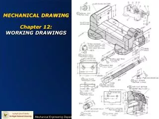
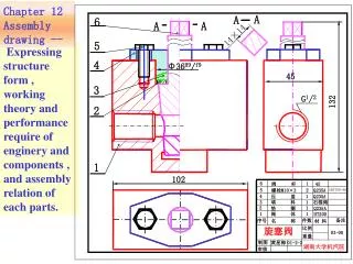
A A A A 14×14 6 5 4 Φ36H9/f9 45 3 G1/2 132 2 1 102 6 1 阀 杆 45 5 2 螺栓M10×3 Q235A GB5780-86 4 1 压 盖 Q235A 3 1 填 料 石棉绳 2 1 垫 圈 Q235A 1 1 阀 体 HT200 备注 名 称 件数 序号 材 料 旋塞阀 比例 03-00 重量 01-2-2 制图 黄星梅 湖南大学机汽院 审核 Chapter 12 Assembly drawing -- Expressing structure form , working theory and performance require of enginery and components , and assembly relation of each parts.
§12-1 Action and Content of Assembly Drawings §12-2 Expressing Method of Parts §12-3 Dimension Note and Technic Requirement of Assembly Drawings §12-4 Serial Number and List of Parts in assembly drawings §12-5 Familiar Assembly Structure and Setting in Machine §12-6 MappingComponents and Making Assembly §12-7 Analysis assembly and Draw Parts Drawings §12-4 Instance
§12-1 Action and Content of Assembly Drawings 12.1.1 Action of Assembly Drawings Firstly make assembly drawings,then, design part according assembly drawings. Designing: According to assembly drawings ,assembly relation and technic requirement, manufacturing parts ,then , assembly machine or components, and checkout and debugging. Manufacture: Installation: Assembly drawing is important technic file for design and assemble. 12.1.1 Content of Assembly Drawings Taking stopcock for example,a assembly drawing ought to include: (1)A set of graph Choosing a set of view ,and using various methods to express operating principle, structure feature of machine or components ,and position relation , assembly relation of each parts, and structure form of mainly parts right ,integrity and syllabify.
(2)Dimension Note perform specs dimension ,mating dimension , installing dimension , collectivity dimension and other important dimension of machine and components. (3)Technic Requirement Note operation criterion and index used in assembly, installation, checkout ,and debugging of machine and components by word and symbol. (4) Serial Number and List of Parts As convenient for organize manufacture and manage, in assembly drawings , every parts should be arranged serial number by order and list in list, filling in their name, material ,number. (5)Title Bar In title bar , filling in name of machine and component , drawing number, scale, design , maker , checker sign.
(1) A set of graph A A A A 14×14 6 5 4 Φ36H9/f9 45 3 G1/2 132 2 1 102 6 1 阀 杆 45 5 2 螺栓M10×3 Q235A GB5780-86 4 1 压 盖 Q235A 3 1 填 料 石棉绳 2 1 垫 圈 Q235A 1 1 阀 体 HT200 备注 名 称 件数 序号 材 料 旋塞阀 比例 03-00 重量 制图 湖南大学机汽院 审核 Section Section Half section Left-view 技术要求: top view
(2)Dimension A A 102 6 1 阀 杆 45 5 2 螺栓M10×3 Q235A GB5780-86 4 1 压 盖 Q235A 3 1 填 料 石棉绳 2 1 垫 圈 Q235A 1 1 阀 体 HT200 备注 名 称 件数 序号 材 料 旋塞阀 比例 03-00 重量 制图 湖南大学机汽院 审核 6 A A Note perform specs dimension ,mating dimension , installing dimension , collectivity dimension and other important dimension of machine and components. 14×14 5 4 Φ36H9/f9 Φ36h9/f9 45 3 G1/2 G1/2 132 Φ36H9/f9 2 1 102 技术要求:
(3) Technic Requirement A A 6 A A 14×14 5 4 Φ36H9/f9 45 3 G1/2 132 2 1 102 6 1 阀 杆 45 5 2 螺栓M10×3 Q235A GB5780-86 4 1 压 盖 Q235A 3 1 填 料 石棉绳 2 1 垫 圈 Q235A 1 1 阀 体 HT200 备注 名 称 件数 序号 材 料 旋塞阀 比例 03-00 重量 制图 湖南大学机汽院 审核 Note operation criterion and index used in assembly, installation, checkout ,and debugging of machine and components by word and symbol. Technic Requirement: It need press trial after installion
(4)Serial Number and List of Parts A A 6 5 4 4 3 3 2 2 1 1 6 6 6 1 1 1 阀 杆 阀 杆 阀 杆 45 45 45 5 5 5 2 2 2 螺栓M10×3 螺栓M10×3 螺栓M10×3 Q235A Q235A Q235A GB5780-86 GB5780-86 GB5780-86 4 4 4 1 1 1 压 盖 压 盖 压 盖 Q235A Q235A Q235A 3 3 3 1 1 1 填 料 填 料 填 料 石棉绳 石棉绳 石棉绳 2 2 2 1 1 1 垫 圈 垫 圈 垫 圈 Q235A Q235A Q235A 1 1 1 1 1 1 阀 体 阀 体 阀 体 HT200 HT200 HT200 备注 备注 备注 名 称 名 称 名 称 件数 件数 件数 序号 序号 序号 材 料 材 料 材 料 旋塞阀 旋塞阀 旋塞阀 比例 比例 比例 03-00 03-00 03-00 重量 重量 重量 01-2-2 01-2-2 制图 制图 制图 黄星梅 黄星梅 湖南大学机汽院 湖南大学机汽院 湖南大学机汽院 审核 审核 审核 A A 14×14 As convenient for organize manufacture and manage, in assembly drawings , every parts should be arranged serial number by order and list in list, filling in their name, material ,number. Φ36H9/f9 45 G1/2 132 102 技术要求:
Title Bar 阀 杆 45 1 6 Q235A 2 螺栓M10×3 5 Q235A 1 4 压 盖 石棉绳 1 3 填 料 1 Q235A 2 垫 圈 HT200 1 阀 体 1 QTY PART NO. MATERIAL ITEM DESCRIPTION SCALE 旋塞阀 03-00 WEIGHT 01-2-2 DRAWN BY 湖南大学机汽院 CHECKED BY
§12-2 Expression Method of Assembly Drawing 12.2.1 Basic Expression Method of Assembly Drawing Rotating view View Basic View Detail View Oblique Drawing Expression Method of Parts Drawings Half Section Detail Section Full Section Cutaway View Oblique section Rotating section Step section Multi-section Section View Superposition section Shift section Emphases:Expression Operation Theory of Assembly;Transmission Route ; Structure Feature;Assembly relation of each parts. 12.2.2 Brushwork of Assembly Drawing 12.2.3 Special Expression Method of Assembly Drawing
Section A A A A 14×14 6 5 4 Φ36H9/f9 45 3 G1/2 132 2 1 102 6 1 阀 杆 45 5 2 螺栓M10×30 Q235A GB5780-00 4 1 压 盖 Q235A 3 1 填 料 石棉绳 2 1 垫 圈10 Q235A 1 1 阀 体 HT200 备注 名 称 件数 序号 材 料 旋塞阀 比例 03-00 重量 制图 湖南大学机汽院 审核 Expression Method of Parts Drawings Half Section Left View 技术要求: Top View GB97.1-02
12.2.2 Brushwork of Assembly Drawing Principal axis Box-body Bearing Cushion ring Shell Cover For two un-contact surface, draw two lines (1) For contact surface ,mating surface with same dimension, draw nothing but one contour line. (2) In section view and cutaway view ,if thickness≤2mm,section line can be replaced by blacking. For two mating surface, draw one line For two contact surface, draw one line
12.2.2 Brushwork of Assembly Drawing (1) For contact surface ,mating surface with same dimension, draw nothing but one contour line. (2) In section view and cutaway view ,if thickness≤2mm,section line can be replaced by blacking. (3)In section view and cutaway view , section line of adjacent parts should incline in different way or have different space for distinguishing parts. In a drawing , incline direction and space of a part should be uniform in different section view and cutaway view.
12.2.3 Special Expression Method of Assembly Drawing Principal axis Cushion ring Shell Cover Bearing Box-body 1.Predigest Brushwork (1)Technics Structure of Parts(Round、Chamfer、Neck and so on ) (2)Rolling Bearing、Standard parts. Omit Round Un-section Bearing Predigest Brushwork Magnify Clearance Bolt Predigest Brushwork 2.Magnify Brushwork Slice parts: Minuteness Space
12.2.3 Special Expression Method of Assembly Drawing Lock Hand Grip 450 Lathe Finial Lock Sleeve Lathe Tailstock 3.Supposition Brushwork (1)Utmost position of running parts (2)Connect and install relation with other parts, but not belong to this part.
12.2.3 Special Expression Method of Assembly Drawing Lathe Guide Installation Relation 3.Supposition Brushwork (1)Utmost position of running parts (2)Connect and install relation with other parts, but not belong to this part. 450
A 12.2.3 Special Expression Method of Assembly Drawing Transmission Route Ⅳ A A Ⅰ A A Ⅲ A Ⅱ Expanded by transmission route 4.Expanded View Ⅰ Ⅰ 床头箱 Ⅱ Ⅱ Three-wheel assembly drawings Supposition Brushwork Ⅲ Express transmission route and assembly relation of framework,supposition by transmission order, cut open and expand along axis by some section. Ⅲ Ⅳ Ⅳ
12.2.3 Special Expression Method of Assembly Drawing A A 5. Disassembly Brushwork and Cut Open along combined surface For example, half section view of gear oil pump left elevation is cut open along combined surface. A-A A-A φ14H7/k6 φ16H7/h6 φ16H7/h6 φ35H8/F7 28.67±0.016 95 φ16H7/h6 φ16H7/h6 φ35H8/F7 50 118 70 95
6.Draw singlepart 圈 13 垫 GB/T97.1-2002 4 Q235A 母 螺 4 GB/T6170-2000 12 Q235A 11 柱 螺 Q235A 1 GB/T898-1988 定 钉 固 螺 1 Q235A 10 母 螺 1 GB/T6170-2000 9 Q235A ZAISi7Mg 阀 帽 8 1 阀 杆 1 7 35 簧 弹 托 1 盘 H62 6 ZAISi7Mg 阀 5 盖 1 垫 1 4 片 弹 簧 1 3 60Mn 2 H62 阀 1 门 ZAISi7Mg 1 阀 体 1 序号 名 称 数量 材 料 备 注 比例 安 全 阀 第 张 共 张 制图 审核 8 4-M6 9 4-φ9 件1B 件1A R8 7 10 6 11 φ20 φ56 φ77 φ60 5 H9/f9 φ26 φ20 12 4 13 技术要求: 3 1.阀门与阀体之间的结合面需经研磨,不漏水和气. 2党阀门关紧后,高压部分能耐压10公斤/平方厘米. 3.为加工表面涂路色油漆. 4.安全阀与管道连接处需加橡胶石棉垫XB350. φ34 2 H7/g6 A 173.5 1 20 A 43 GB/T71-1985 B φ77 湖南大学
12.2.4 Draw Assembly Drawing by Parts Drawing 装配体的安放位置,应与工作位置相符合,这样对于设计和指导装配都会带来方便。图为水平位置。为了清楚地反映主要的装配关系和工作原理,主视图选择半剖视。 装配体的基本表达方法 装配体的特殊表达方法 根据确定的主视图,再选取能反映其它未表达的装配关系,外形及局部结构的视图。如旋塞阀的外形结构须采用俯视图,左视图。反映阀杆的结构采用局部视图。 Assembly body compose of many parts,we can put together assembly drawing by parts drawing . Taking stopcock for example, discuss the way of making assembly drawing. 1.Understanding assembly relation to determine express method of assembly drawing. (1)Realize operation theory and structure characteristic of assembly body. (2)Realize instruction book, understand assembly sketch map. Sketch Map: Draw assembly relation, operation theory,transmission route, part number by simple line. (3)Choose proper express method 2 .Choose View (1)Choose main view in assembly drawing (2)Choose other view
12.2.5 Illustration of Assembly Drawing valve handle Stopcock Graphic Model Bolt Gland Bush The figure is stopcock which is made up of valve and other standard piece. When valve is enclosed in pipeline, we can control flow on-off by turning valve handle. Filling Cushion ring Valve Body
12.2.5 Illustration of Assembly Drawing Analysis Structure Connecting Relation Assembly Route Part Number
12.2.5 Illustration of Assembly Drawing 6 5 5 4 3 2 出 入 1 Operation Theory: Stopcock is a equipment controlling flow on-off. The figure show the estate of opening, flow come form right ,go out to left .If turning valve grip 90 ,the stopcock will be off. There is filling 3 (asbestos cord)between valve grip 6 and valve body 1.Screw down bolt 5 ,then compact by press pole for closed . Working position : valve grip 6 is uprightness, entrance passage is horizontal position, show by figure. According to axonometric drawing,sketch map and parts drawing of stopcock , draw assembly drawing in A3 drawing. 1 Valve Body ; 2 Cushion Ring; 3 Filling( Asbestos Cord); 4 Gland Bush ; 6 Valve Grip 5 Bolt GB5780-86-M10×30(Q235A);
Installation Process of Stopcock Pay attention to align hole axis and keep tape uniformly Firstly install valve grip
Installation Process of Stopcock Pay attention to align valve grip axis and end surface. Firstly install valve grip Install cushion ring
Installation Process of Stopcock Gland bush compact lock ring ,and there should be clearance between cover board and valve body. Firstly install valve grip Install cushion ring Install lock ring and gland bush
Installation Process of Stopcock Firstly install valve grip Install cushion ring Install lock ring and gland bush Install bolt
Working Process of Stopcock Rotate 90。 Off On Back Front
12.2.6 Step of Making Assembly Drawing 1. According to express scheme,choose proper scale,arrange view position. Pay attention to leave enough space for making title bar , technic requirement and noting dimension. 2.Firstly, draw main axis (assembly main stem), symmetry axis ,and basic line of left view( some parts surface) . At first ,draw main view, then, complete other view . When making cutaway view , according to assembly main stem , draw every parts one by one.
(1)Draw main axis ,symmetry axis and basic line of each view . 旋塞阀 比例 03-00 重量 制图 湖南大学机汽院 审核
(2) Draw contour line of main parts,the three view relate with each other. 旋塞阀 比例 03-00 重量 制图 湖南大学机汽院 审核
Analysis orientation of valve grid (3) Draw contour line of main parts Align Tape 旋塞阀 比例 03-00 重量 制图 湖南大学机汽院 审核
(4) Draw Cushion ring and Filling 旋塞阀 比例 03-00 重量 制图 湖南大学机汽院 审核
(5) Draw gland brush 旋塞阀 比例 03-00 重量 制图 湖南大学机汽院 审核
(6)Draw Bolt (7)Check ,Overstriking,draw section line, note dimension, make part serial number, fill in list and technic requirement 旋塞阀 比例 03-00 重量 制图 湖南大学机汽院 审核
A A 6 A A 3 14×14 2 1 6 1 阀 杆 45 5 2 螺栓M10×3 Q235A GB5780-86 4 1 压 盖 Q235A 3 1 填 料 石棉绳 2 1 垫 圈 Q235A 1 1 阀 体 HT200 备注 名 称 件数 序号 材 料 旋塞阀 比例 03-00 重量 制图 湖南大学机汽院 审核 5 4 Φ36H9/f9 45 G1/2 132 102 技术要求: 安装后,需要进行压力试验。 旋塞阀 比例 03-00 重量 制图 湖南大学机汽院 审核
Eg2:Draw Assembly Drawing by Parts Drawing 9 8 7 6 10 5 11 12 13 4 3 2 1 1.Valve Body;2.Valve ;3.Spring 4. Filling Piece ; 5. Valve Cap ;6.Spring Tray;7.Screw;8.Bonnet;9.Nut;10.Bolt;11.Bolt;12.Nut;13.Cushion Ring
Operation Theory of Safety Valve 9 8 6 7 10 5 11 12 13 4 3 2 1 When oil press is in gear Safety valve is used to control oil press in its loop. When oil press is in gear, press oil entrance from down nozzle,then, pour to right nozzle 出口 入
Operation Theory of Safety Valve 9 8 Valve handle Valve Cap 7 6 10 Adjust Spring 5 11 12 13 4 3 2 1 When oil press exceed bound When oil press exceed bound, press oil will overcome spring press to open valve and reflow oil pool form left pipe, for keeping oil press. 出口 Oil pool 入
9 8 Valve handle Valve Cap 7 6 10 Adjust Spring 5 11 12 13 4 3 2 1 Adjust of spring pro-press We can adjust oil press by screw,at first, open valve cap8,loose nut9,then, screw screw 7 to adjust the press of spring 3,screw down nut9, avoid valve staring,and cover valve cap 8. Hoist oil press Unwanted oil Exit Oil pool 入
Assembly Process of Safety valve 1Read part drawing, imagine graphic model of every parts.
Assembly Process of Safety valve 1Read part drawing, imagine graphic model of every parts.
Assembly Process of Safety valve 2. Analysis connect and assembly relation
Relation of two parts Firstly install valve and spring Spring Spring orientation Valve Analysis detail structure and notice mating relation for ensure oil press equalizing hole. Analysis detail structure and notice mating relation for ensure oil press disassembly mounting hole
Orientation Relation of two parts Install spring tray, screw, screw cap, bonnet Install lock bolt
Analysis assembly relation ,choose express method ,view number
(1)Draw datum,and main valve body 比例 安 全 阀 第 张 共 张 湖南大学 制图 审核