Download
1 / 25
250 likes | 470 Views
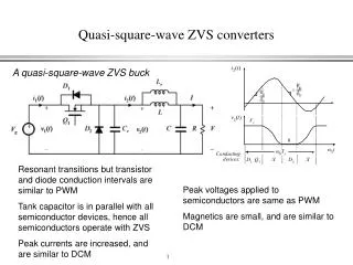
Phase Control Techniques and their implementation on Wave Energy Converters Torkel Bjarte-Larsson. CeSOS Norwegian University of Science and Technology NTNU Trondheim, Norway. Outline. Practical implementation Resonance turning Continuous control: Reactive Discrete control: Latching

E N D
Phase Control Techniques and their implementation on Wave Energy ConvertersTorkel Bjarte-Larsson CeSOS Norwegian University of Science and Technology NTNU Trondheim, Norway
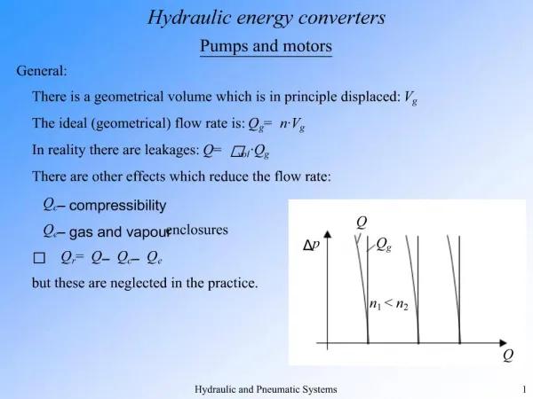
Outline • Practical implementation • Resonance turning • Continuous control: Reactive • Discrete control: Latching • Phase control: Physical explanation • Electric analogy (reactive) • Mathematical condition (reactive) • Numerical results for wave-power absorption by heaving semisubmerged sphere. • Power conversion by laboratory model.
Two conditions for absorbing maximum power • The oscillation velocity must be in phase with the excitation force. • The amplitude of the oscillation must be adjusted to the optimum value. (The absorbed power is equal to the power reradiated into the sea).
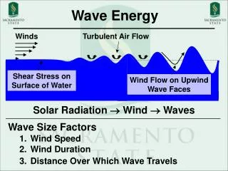
Resonance turning • The natural period of the device should at all times be turned to the period of the wave. • Changing the mass of the oscillating body by pumping water in and out of ballast tanks. • The buoy reacting against an internal mass by stiffness modulation.
Continuous control • During the mid 1970s it was purposed independendently by Salter and by Budal to apply control engineering for optimising the oscillatory motion of a wave-energy converter in order to maximise the energy output. • For the practical implementation it was proposed to use a controllable power take-off device, for instance a combined generator-and-motor or turbine-and-pump. • Reference: • Budal, K. And Falnes, J., 1977. Optimum operation of improved wave-power converter. Marine Science Communications, Vol 3, pp 133-150. • Salter, S.H., Jeffery, D.C., and Taylor, J.R.M., 1976. The architecture of nodding duck wave power generators. The Naval Architect, pp 21-24
Continuous control • The energy used by the motor should not be considered as lost, since it has been used so that the converter is able to produce more energy in the future (later in the wave period).
Continuous control of double acting piston This system allows continuous control of the velocity of the piston. But requires that the motor/pump is able to handle a very large flow.
Electromagnet for latching and hydraulic power take-off • Hydraulisk pumpe benyttes for energiuttak • Låsemekanismen for fasestyring består av jern skinner som går gjennom luftgapet til en elektrisk magnet. PICT0015.JPG
Optimal phase at resonance Phase control by latching Wave and heave motion of power buoy t or by reactive control 6EWTEC 2005-08-31 TB-L&JF/NTNU
Phase control and amplitude control • Instead of the terms phase control and amplitude control the terms reactive control and load control are used. • Amplitude control is also termed resistive control. • When both phase and amplitude of the oscillation are controlled, the term complexconjugate control is also used. • Optimum control include both phase control and amplitude control.
Nilsson & Riedel Electric Circuits: • The apparent power, or volt-amp,requirement of a device designed to convert electric energy to a nonelectric form is more important than the average power requirement. Although the average power represents the useful output of the energy converting device, the apparent power represent the volt-amp capacity required to supply the average power.
Accumulation of energy by oscillating body. reactive control latching control no control (passive) By reactive control, energy flow through the conversion machinery has to be reversed during part of the wave cycle. 6EWTEC 2005-08-31 TB-L&JF/NTNU
Theoretical (numerical) study of heaving semi-submerged sphere Diameter 2a = 10 m smax = 0.6 a = 3 m Natural heave period = 4.3 s 6EWTEC 2005-08-31 TB-L&JF/NTNU
latching Amplitude (m) of incident wave Absorbed power (MW) from wave of period T = 9 s Example: A = 0.5 m: Preact = 172 kW Platch = 137 kW Ppassiv = 24 kW 6EWTEC 2005-08-31 TB-L&JF/NTNU
Average slope: Preact = 172 kW Platch = 137 kW Ppassiv = 24 kW A = 0.5 m, T = 9 s Absorbed energy Curve slope = instantaneous power 6EWTEC 2005-08-31 TB-L&JF/NTNU
Heaving buoy. Cylinder with hemispherical bottom. Arranged to slide along a vertical strut. 6EWTEC 2005-08-31 TB-L&JF/NTNU
Heaving buoy of diameter 0.14 m and natural heave frequency 1.1 Hz, tested in a wave channel 0.33 m wide. Power take-off by piston pump lifting water to an elevated reservoir. Two vertical rails may be latched by two electromagnets on the lower fixed platform. 6EWTEC 2005-08-31 TB-L&JF/NTNU
Relative absorbed power and useful powerwithout and with phase-control versus heave/wave amplitude ratio absorbed useful Amplitude ratio |s/A| decreases by increasing the load (increasing the pump head). Curves are fits to a mathematical model. 6EWTEC 2005-08-31 TB-L&JF/NTNU
Concluding remarks. • Compared to reactive control, latching control is slightly sub-optimum, but avoids the necessity for reversing the power flow. • The relative benefit of applying control (reactive or latching) is strongly dependent upon the width of the resonance curve, that is, upon the size of the oscillating body compared to the wavelength. • The model experiment demonstrates the need for developing a guiding system with less friction. 6EWTEC 2005-08-31 TB-L&JF/NTNU
THE END 6EWTEC 2005-08-31 TB-L&JF/NTNU
Outline: • Phase control and amplitude control • Reactive control (optimum) and latching control (sub-optimum). • Numerical results for wave-power absorption by heaving semisubmerged sphere. • Heaving vertical cylinder: • Hydrodynamical parameters approximated. • Power conversion by laboratory model. • Concluding remarks. 6EWTEC 2005-08-31 TB-L&JF/NTNU
Sketch of the floating wave-energy converterrounded edge geometry Water depth h = 25 m 3.65m 10.15m 3.3m 0.3m 4m 6EWTEC 2005-08-31 TB-L&JF/NTNU
Radiation resistance versus frequency in normalised units. numerical (AQUADYN) limit for = 0 Upper curve: approximate empirical elementary-function deep-water formula. Lower curve: same formula, but with k = k() for water depth h = 25 m.