Download

1 / 30
300 likes | 439 Views
The readout system of the MVD-demonstrator for beam test. C.Schrader , S. Amar-Youcef, M. Deveaux, D. Doering, C. Müntz, S. Seddiki, P.Scharrer, J. Stroth, T. Tischler. C.Schrader; Oct. 2009 , CBM Collaboration Meeting. Outline:. concept of the readout chain

E N D
The readout system of the MVD-demonstrator for beam test C.Schrader, S. Amar-Youcef, M. Deveaux, D. Doering, C. Müntz, S. Seddiki, P.Scharrer, J. Stroth, T. Tischler C.Schrader; Oct. 2009, CBM Collaboration Meeting
Outline: • concept of the readout chain • results of the laboratory tests • beam time preparations • discussion of the real time data processing • data protocol for beam test • status and conclusion C.Schrader; Oct. 2009, CBM Collaboration Meeting
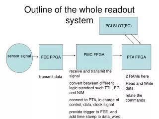
labour readout chain readout components ► lab results ► beam test setup ► data processing ► data protocol Trb2 (TRBnet) demo-AUX analogue output sync. signals demo-AUX MAPS add-on board or MAPS_add-on board monitoring data transfer: I/O-card data transfer: OP-link Trb2 status: developed by IKF, fully tested file server I/O-card or OP-link C.Schrader; Oct. 2009, CBM Collaboration Meeting
the main platforms readout components ► lab results ► beam test setup ► data processing ► data protocol demo-AUX board for temperature sensors flex print cable rigid- flex 2x MIMOSA-20, parallel readout, 320 x 640 pixel/frame, 50MHz 2.4Gbit/s, uncompressed • MAPS add-on board • platform to study online data sparsificationfor data reduction • (by FPGA) • close to hardware for chip integration in future times • analog front-end and a digital front-end • 12 bit analogue digital converter • compatibility with HADES DAQ (Trb2) for testing purposes • demo-AUX board • signal amplification and buffering • low voltage regulated power supply • repeater/splitter for clock splitting into two chips • JTAG interface for slow control of chip • one-wire temperature measurement
results of Mi20 on DemoFlex readout components ►lab results ► beam test setup ► data processing ► data protocol The spectra of a 55Fe-source with the Kα-peak (5,9 keV) is used as reference and calibration. Hit distribution: Events over threshold/1000 frames Entries row Kα (55Fe ) Entries Signal [ADC] column mesh structure and bonding pads are visible C.Schrader; Oct. 2009, CBM Collaboration Meeting
results of Mi20 on DemoFlex readout components ►lab results ► beam test setup ► data processing ► data protocol see talk of Samir • High noise of 38e because of common mode noise After filtering of common mode: Noise = 24e • online/offline filter • active flex-print-cable with capacities C.Schrader; Oct. 2009, CBM Collaboration Meeting
ready for beam test readout components ►lab results ► beam test setup ► data processing ► data protocol The relevant test to reconstruct reference tracks takes place at CERN-SPS together with the IPHC group. • goals for the IKF group • to test the complete readout chain from chip to data analyzing software • to study online data sparsification, which are dictated through the CBM requirements • detection affiance of >95% should be achieved, which is limited by the used Mi20 sensor • measurements by -10°C • goals for the IPHC group • the ladder is able to rotate to study the hit correlations on the two sides of the ladder module at different incident angels • measurements by room temperature • used by a FPGA based analogue to digital converter board (TNT) Both readout systems should be running separately in case of setup failure. Synchronization is needed for the data alignment. C.Schrader; Oct. 2009, CBM Collaboration Meeting
beam test setup readout components ►lab results ► beam test setup ► data processing ► data protocol see talk of T. Tischler TAPI telescope beam hole IKF setup with DemoAUX, Mi20 and cooling support, MAPS add-on board beam IKF Plume scintillator IPHC setup with DemoAux, no cooling support, angel adjustment, 1x TNT board reference planes 2x Mi18, with 2x TNT boards reference planes 2x Mi18, with 2x TNT boards trigger unit C.Schrader; Oct. 2009, CBM Collaboration Meeting
pipelined algorithms raw data readout components ►lab results ► beam test setup ► data processing ► data protocol step1: data conversion step2: ADC calibration Input: 2x MIMOSA-20, parallel readout, 320 x 640 pixel/frame, 50MHz 2.4Gbit/s, real-time application in stream mode C.Schrader; Oct. 2009, CBM Collaboration Meeting
correlated double sampling (CDS) raw data readout components ►lab results ► beam test setup ► data processing ► data protocol step3: CDS is thedifference between actual pixel value and the value of the previous frame C.Schrader; Oct. 2009, CBM Collaboration Meeting
zero suppression readout components ►lab results ► beam test setup ► data processing ► data protocol step4: the 16bit raw data word is replaced by the hit pixel address with the following 2 or 3 pixels (2x 16bit word for one hit mask) rawdata see talk of of S. Seddiki Output: uncompressed: 2.4Gbit/s compressed: ~200 Mbits/s C.Schrader; Oct. 2009, CBM Collaboration Meeting
trigger mode raw data readout components ►lab results ► beam test setup ► data processing ► data protocol rawdata choice of continuous readout or triggered readout with data selection step5: RAM acts as FIFO to buffer the data output C.Schrader; Oct. 2009, CBM Collaboration Meeting
data selection raw data readout components ► lab results ► beam test setup ► data processing ► data protocol parallel: storage for raw data, to compare online with offline data algorithms a switch decide between online edit data and raw data C.Schrader; Oct. 2009, CBM Collaboration Meeting
online data sparsifications readout components ► lab results ► beam test setup ► data processing ► data protocol 16bit 16bit 2x 16bit 2x 16bit+ 16bit C.Schrader; Oct. 2009, CBM Collaboration Meeting
Trigger and timing readout components ► lab results ► beam test setup ► data processing ► data protocol • The test system components: • rely on different readout boards • show different readout times Telescope (TNT): Readout time ~ 4 ms Plume PLUME (TNT): Readout time ~ 2 ms IKF scintillator MVD-Demonstrator: Readout time ~ 2 ms reference planes 2x Mi18, with 2x TNT boards reference planes 2x Mi18, with 2x TNT boards Need a synchronization by trigger number and time stamps
What means trigger pile-up readout components ►lab results ► beam test setup ► data processing ► data protocol … … frame n-1 frame n frame n+1 trigger not of interest, no readout Needed for track 1 Needed for track 2 Needed for both tracks 2 frame HDR
Trigger and timing readout components ► lab results ► beam test setup ► data processing ► data protocol Cases: • No trigger pile-up in the readout time of telescope and DUT • All devices have information on the track causing by the trigger • Trigger pile-up in the telescope, not in the DUT • Second track will show up in different frames in DUT and telescope • Needs concept for good track matching • Trigger pile-up in both devices • Make sure that both devices receive the track • Remember Eigen-time of the individual pixels Complex with respect to traditional MAPS-beamtests Synchronization by frame-number is not possible
Synchronization approach Data Data readout components ► lab results ► beam test setup ► data processing ► data protocol Clk Trigger Demonstrator MAPS-Board Start trigger Scintillator TNT-Master Trigger Telescope Time Stamp Time Stamp TriggerNmb. TriggerNmb. HDD-1 HDD-2 Offline analysis (CBMRoot & MAF) Both “Event/Frame based” Build frames/event by trigger number see talk of Samir Nice training for the untriggered readout of CBM
Summary and conclusion The electronic readout chain of the MVD-digitizer has been validated Analog design performances were reached (if common mode filter available) Beam test of the digitizer is scheduled for early November at CERN – SPS Preparation of software and hardware is on a good track
Thank you C.Schrader; Oct. 2009, CBM Collaboration Meeting
data protocol readout components ►lab results ► beam test setup ► data processing ► data protocol HDR new frame modus 12 11 10 9 8 7 6 5 4 3 2 1 0 0 0 CDS 0 1 trigger 1 0 raw 1 1 zero ADC number frame counter error 15 14 13 0: false 1: valid • separate HDR for each channel • readout modus is selected • absolute time calculation by HDR • relative HDR number in case of HDR lost • online monitoring by error bit 0: data 1: HDR 0: new frame 1: trigger/time C.Schrader; Oct. 2009, CBM Collaboration Meeting
data protocol readout components ►lab results ► beam test setup ► data processing ► data protocol raw/CDS data word 12 11 10 9 8 7 6 5 4 3 2 1 0 12 bit data word (raw/CDS): pixelwise readout ADC number 15 14 13 0: false 1: valid • readout is parallel for each ADC channel • exact trigger position by trigger marker • exact trigger arrival time 0: data 1: HDR trigger marker C.Schrader; Oct. 2009, CBM Collaboration Meeting
data protocol readout components ► lab results ► beam test setup ► data processing ► data protocol trigger stamp 12 11 10 9 8 7 6 5 4 3 2 1 0 0: trigger counter 1: time stamp trigger counter 15 14 13 • 36bit trigger counter (3x12bit) • ADC channel independent • exact trigger position by trigger marker in a pixel word • crosscheck to marked pixel in case of data losing • reference for offline analyze 0: false 1: valid 0: data 1: HDR 0: new frame 1: trigger/time C.Schrader; Oct. 2009, CBM Collaboration Meeting
data protocol readout components ►lab results ► beam test setup ► data processing ► data protocol time stamp 12 11 10 9 8 7 6 5 4 3 2 1 0 0: trigger counter 1: time stamp clock counter 15 14 13 • 36bit clock counter (3x12bit) • ADC channel independent • to calculate the start and trigger offset to the • reference planes • exact trigger arrival time • reference for offline analyses 0: false 1: valid 0: data 1: HDR 0: new frame 1: trigger/time C.Schrader; Oct. 2009, CBM Collaboration Meeting
readout dataflow readout components ►lab results ► beam test setup ► data processing ► data protocol • each frame creates an HDR • time calculation by HDR and trigger event • relative frame number in case of HDR lost • absolute trigger number • (enables restart and data comparison) dataflow • when • HDR: throughout data taking • trigger data/marker : whenever trigger signal arrives • trigger counter/time stamp: in delay of the readout C.Schrader; Oct. 2009, CBM Collaboration Meeting
status of the readout system data processing: in progress tested hardware: • two ladder systems are build up and tested in the lab • trigger mode is tested noise reduction: • additional filter will be implemented in the pipeline algorithm (on FPGA) • modification on flex-print cable (capacitor) C.Schrader; Oct. 2009, CBM Collaboration Meeting
trigger readout mode readout components ►lab results ► beam test setup ► data processing ► data protocol … … frame n-1 frame n frame n+1 trigger not of interest, no readout trigger; theactualpixelwhichisreaded out ismarkedby an additional bit trigger marked pixel readed out frame HDR second trigger data C.Schrader; Oct. 2009, CBM Collaboration Meeting
sensor ► readout chain►readout components ►data processing mimosa20 demonstrator: 2x MIMOSA-20, parallel readout, 320 x 640 pixel/frame, 50MHz 2.4Gbit/s, uncompressed • platform to study online data specification for data reduction • close to hardware for chip integration in future times • compatibility with HADES DAQ (Trb2) for testing purposes functionality of the add-on board This data rate is too high for data storage systems online data reduction developed by IKF electronic workshop add-on board with a FPGA as reconfigurable hardware status: 12 layer board is completed and tested
components of the add-on-board sensor ► readout chain►readout components ►data processing 4x diff. analogue pixel data signals LVDS digital sync. signals I/O from demo-Aux • analogue readout chain for the • output signal of the two chips • digital chain for chip controlling • and clock distributions • real-time performance for data-processing • data transfer interface towards • the Trb2-board add-on-board
ZERO: DATA (ZERO): Address + Number of consec. fired pixels Data valid Submatrix 15 14 13 12 11 10 9 8 7 6 5 4 3 2 1 0 6 bit: (26=64) for address in 'line' 2 bit: max 3 consecutive pixels F-HDR=0 Newline / Charge ADC NUMBER 0 Charge 1 Newline NOTE: each submatrix has its own newline counting!