Download

1 / 28
280 likes | 429 Views
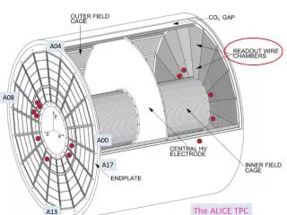
ALICE TPC field cage status. Sardinia May 2004 Michael Hoch Cern-TA2. Field Cage Feb. 04. Strips on the muon side completed. Temperature sensors inside the volume. 4-wire Pt 1000 sensors purchased 50 pieces with 1m wire Calibrated to two calibr. reference pt1000 ( ± 3mK at 20 degree)

E N D
ALICE TPC field cage status Sardinia May 2004 Michael Hoch Cern-TA2
Field Cage Feb. 04 Strips on the muon side completed
Temperature sensors inside the volume • 4-wire Pt 1000 sensors purchased • 50 pieces with 1m wire • Calibrated to two calibr. reference pt1000 • (±3mK at 20 degree) • Calibration range between ~7- 25 degree • Residuals fit by Danilo -> ±10mK
Shaft side temperature sensors • Glued on to the skirt of the 18 sectors
Muon side temperature sensors • 4 sensors at the inner cylinder
Shaft side connectors and feed-troughs • Pt 1000 • Skirt supply • Last resistors guard ring chains • Last resistors R-rods • Last strip supply
Field Cage March 04 Once more HV test (1500V between strips) & cleaned -Muon side completed-
Displacement rails mounted turning clamp
Resistor rod RR final assembly
Resistor selection Resistor dispersion results in a field distortion of maximal 40mm (presented by Danilo; status field cageFeb. 04)
Resistor Rods shaft side Hooks on the outlet side >> << Resistor Rod outlet on the endplate
Resistor rod shaft side HV tests • 1500V between hooks • 15kV between Al-guard rings • 120kV in the test box
Laser system control Laser beam mapping by Borge Cross checked by Rainer
central membrane • 0.8mm wire connecting the outer and inner CE-flange • Conductive glue -> CE-flange-Al-Mylar foil
I-bar survey: BCAM system test Bicam system tests with Panos Christakoglou
Outlook: • Installation of 18 pt1000 inside the volume • Electrical connection/ feed troughs • Test HV: • 1500V between each strip • 120kV • Cleaning of the volume • Installation of external temperature sensors • Turning of the field cage, closure of the volume • He & final integral leak test • Installation of the charge to the sliding feeds
Thank you for your attention TPC meeting Sardinia May 2004 Michael Hoch CERN TA2