Download
1 / 52
520 likes | 658 Views
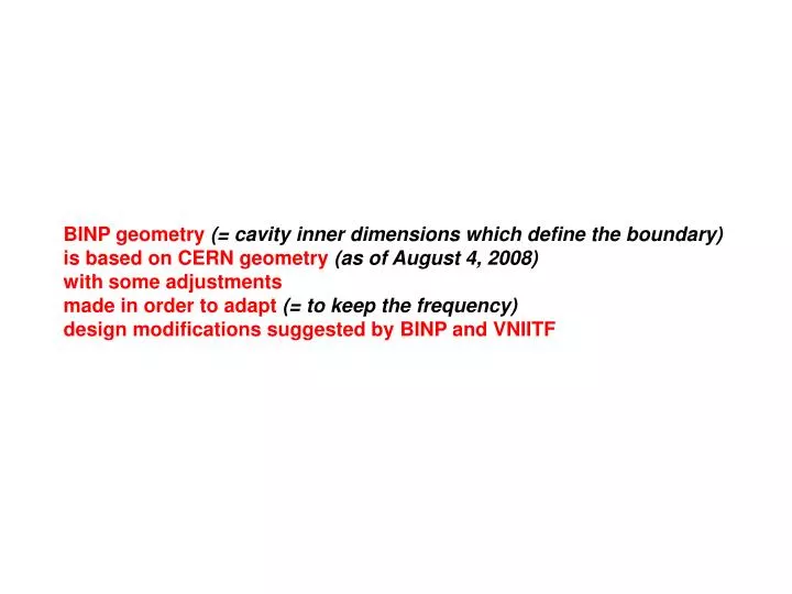
BINP geometry (= cavity inner dimensions which define the boundary) is based on CERN geometry (as of August 4, 2008) with some adjustments made in order to adapt (= to keep the frequency) design modifications suggested by BINP and VNIITF. Constant definition (Superfish style).

E N D
BINP geometry(= cavity inner dimensions which define the boundary) is based on CERN geometry (as of August 4, 2008) with some adjustments made in order to adapt(= to keep the frequency) design modifications suggested by BINP and VNIITF
Constant definition (Superfish style)
Dependent variable Constant for all tanks Constant for tanks 1-9 and 10-21 Variable CERN geometry (as of August 4, 2008)
Constant for all tanks Constant definition (Superfish style) Constant for tanks 1-9 and 10-21 Variable Dependent variable
BINP geometry(= cavity inner dimensions which define the boundary) is based on CERN geometry (as of August 4, 2008) with some adjustments made in order to adapt(= to keep the frequency) design modifications suggested by BINP and VNIITF • Design modifications: • Drift tube to stem connection • Gridded port for an ion pump • Waveguide input coupler CERN geometry BINP geometry
Design modifications / Drift tube to stem connection Cylinder machined from a sphere BINP prototype design Conjoint cylinders CERN prototype design Drift tube to stem connection requires forming mating cylinder on the drift tube
Design modifications / Gridded port for an ion pump Cu-plating 10.5 ISTC prototype 100 DN100CF (STDVFUHV0052) Cu-plating CERN hot model 100 DN100CF
Design modifications / Waveguide input coupler port ISTC prototype Very difficult access to the nuts M6 thread, studs Easier access to the nuts M8 thread, tapped holes, studs or bolts Easy access to the nuts M8 thread, studs or bolts Same HELICOFLEX dimensions as for DTL and PIMS structures
3D simulations Each accelerating cavity is calculated with detuned coupling cavity (-ies) Sphere on a drift tube is accounted. Vacuum gridded port is accounted (1st and 3rd tanks in each module). Waveguide coupler port is accounted (2nd tank in each module) m = 1…7 – module number Tank # 3m-2 Tank # 3m-1 Tank # 3m 303 x 50, R25 (-28kHz for tank #1)
Constant definition (Superfish style)
Dependent variable Constant for all tanks Constant for tanks 1-9 and 10-21 Variable Variable Dependent variable Changes are highlighted BINP geometry
Differences are within 1 mm CERN - BINP geometry
Cavity parameters from 3D simulations BINP geometry (hereinafter)
More realistic, but we better scale the values measured on the prototype …
ISTC prototype: Tank 1 Q0 = 38 080 Tank 2 Q0 = 37 600
Ez field on tank axis (z) from MWS Normalization Emax = 1
Ez field on tank axis (z) from MWS Normalization Emax = 1
L1 = 695.3 mm Drift tube1 = 198.6 mm Gap1 = 71.5 mm Nose cone1 = 41.8 mm Tank #1 L21 = 1 037.1 mm Drift tube21 = 238.2 mm Gap21 = 129.3 mm Nose cone1 = 86.4 mm Tank #21 Ez field on tank axis (z) from MWS
Normalization Emax = 1 E0 E0LT Tanks of a single module are highlighted
avr gap-to-gap center distance (within a single tank) 1.5out gap-to-gap center distance (two adjacent tanks in a module) E0 has to satisfy avr = gap-to-gap center distance (within a single tank) 1.5out = gap-to-gap center distance (two adjacent tanks in a module) Tanks of a single module are highlighted Equal E0 in the tanks of a module
E0 has to satisfy avr = gap-to-gap center distance (within a single tank) 1.5out = gap-to-gap center distance (two adjacent tanks in a module) Equal E0 in the tanks of a module
Q0 = 0.7 Q0 MWS Equal E0 in the tanks of a module
avr gap-to-gap center distance (within a single tank) CERN set of E0 1.5out gap-to-gap center distance (two adjacent tanks in a module) CERN set of E0 Probably the definition of “tank length” is different (?)
Another field distribution with equal Emax in the tanks of a module
avr gap-to-gap center distance (within a single tank) 1.5out gap-to-gap center distance (two adjacent tanks in a module) Emax has to satisfy avr = gap-to-gap center distance (within a single tank) 1.5out = gap-to-gap center distance (two adjacent tanks in a module) Another field distribution with equal Emax in the tanks of a module
Another field distribution with equal Emax in the tanks of a module
3D simulations of specified geometry (without tuners) lead to what frequency?
Tuning range of a single tuner x 84 Tuner midposition + tuner at its midposition +100 kHz + Total frequency shift by a single tuner -100 kHz Frequency shift Df1(x) by a single tuner (measured on the ISTC prototype tank 2) is plotted in magenta Tuners pulled out of the cavity Tuners protrude into the cavity Each tuner position
Tuning sequence Tanks are made with certain accuracy leading to a frequency uncertainty (even if we assume that the drift tubes are machined precisely). Tanks will be measured with installed aluminum dummy drift tubes with “precisely” known (measured after machining) dimensions similar (but not necessarily equal) to those of real drift tubes. Dimensions of copper drift tubes required to bring the frequency of particular tank to the design value will be extrapolated from the measurements with aluminum dummy drift tubes. Final frequency error of a tank with copper drift tubes depends on the precision of this extrapolation and on the drift tube final machining accuracy. Could we relax the tolerances on the tanks manufacturing? No, because we do not want drift tubes to be substantially different from the design. No, because after few first tanks we might gain enough experience and eliminate “measure-extrapolate-machine” sequence, although unlikely. Could we eliminate tuners as we adjust drift tube dimensions to a particular tank actual dimension? No, because even if we know exactly (with extrapolation precision) what ideal drift tube we need, we only can get it within manufacturing accuracy.
Tank 2D simulations ? To be compensated by drift tube re-machining FLAT_length manufacturing precision is considered as max error in R coordinate of nose cone (NC) machining starting point (MSP) which leads to an equal radial “displacement” of the entire nose cone
Tank 2D simulations To be compensated by drift tube re-machining FLAT_length manufacturing precision is considered as max error in R coordinate of nose cone (NC) machining starting point (MSP) which leads to an equal radial “displacement” of the entire nose cone
Drift tube 2D simulations ? DT_FLAT_length manufacturing precision is considered as max error in R coordinate of DT nose cone (NC) machining starting point (MSP) which leads to an equal radial “displacement” of the entire drift tube nose cone To be compensated by tuners
Drift tube 2D simulations DT_FLAT_length manufacturing precision is considered as max error in R coordinate of DT nose cone (NC) machining starting point (MSP) which leads to an equal radial “displacement” of the entire drift tube nose cone Relaxed by a factor of 2 against the Workshop value To be compensated by tuners
Tuning range of 2 equally positioned tuners x 84 Total frequency shift by equally positioned 2 tuners Doubled frequency shift 2Df1(x) by a single tuner (measured on the ISTC prototype tank 2) is plotted in magenta Tuners pulled out of the cavity Tuners protrude into the cavity Each tuner position
ISTC prototype tank 2 No tuners – ports are blank terminated At least 1 tuner is pulled out of the cavity and hidden inside the port Measurements with various combinations of 2 fixed tuners of different lengths
ISTC prototype tank 2 No tuners – ports are blank terminated At least 1 tuner is pulled out of the cavity and hidden inside the port by running medians over a window of 3 neighboor data points Measurements (ISTC prototype tank 2, 2 tuners) Calculations (Linac4 tank 1, single tuner) Same plot as the previous one, but with data points smoothing
Fixed tuner – CERN design (SPLACTUF0012) BINP design is similar to CERN design, but without groove – no spring contact is foreseen AC 84 CC 59 AC 85 CC 60 Copper piston Calculations (Linac4 tank 1, single tuner, without spring contact) Accelerating cavity – DN100CF (STDVFUHV0094) Coupling cavity – DN63CF (STDVFUHV0028) Calculations (Linac4 tank 1, single tuner, with spring contact)
Coupling cell 2D simulations Lcc Rcc Rcco Rcci dcc Dcc gcc
Coupling cell 2D simulations Lcc Rcc Rcco Rcci dcc Dcc gcc
Coupling cell tuning 3D simulations (MWS) Detuned cavities to account coupling cell field distortion due to the coupling slots Cutting plane Coupling cell
Coupling cell tuning 3D simulations (MWS) Total frequency shift by equally positioned 2 tuners was calculated Lcc x Rcc 59 Rcco Rcci dcc Dcc gcc
Coupling cell tuning 3D simulations (MWS) Tuners midposition +783 kHz + -783 kHz Total frequency shift by equally positioned 2 tuners Doubled frequency shift 2Df1(x) by a single tuner (measured on the ISTC prototype) is plotted in blue Tuners pulled out of the cavity Tuners protrude into the cavity Each tuner position
Coupling cell tuning 3D simulations (MWS) Total frequency error due to manufacturing accuracy = 787 kHz Tuners midposition +783 kHz + -783 kHz Total frequency shift by equally positioned 2 tuners Doubled frequency shift 2Df1(x) by a single tuner (measured on the ISTC prototype) is plotted in blue Tuners pulled out of the cavity Tuners protrude into the cavity 2 tuners + careful machiningare necessary Each tuner position
Coupling cell tuning 3D simulations (MWS) Tuners midposition + CC gap = 21.24 mm = f0 + 733 kHz f0 f (no tuners and no tuner ports) Calculated coupling cell frequency with no tuners is 352.2 MHz at CC gap of 21.36 mm … does not agree with the measurements on ISTC prototype, needs to be understood