Download
1 / 12
120 likes | 299 Views
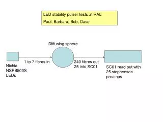
LED stability pulser tests at RAL Paul, Barbara, Bob, Dave. Diffusing sphere. 1 to 7 fibres in. 240 fibres out 25 into SC01. Nichia NSPB500S LEDs. SC01 read out with 25 stephenson preamps. Fibres to inject into diffusing sphere.

E N D
LED stability pulser tests at RAL Paul, Barbara, Bob, Dave Diffusing sphere 1 to 7 fibres in 240 fibres out25 into SC01 NichiaNSPB500SLEDs SC01 read out with 25 stephenson preamps
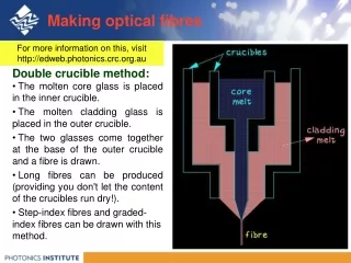
Fibres to inject into diffusing sphere Quartz fibreSupplied by Applied Photonics, manufactured by Laser Components. The Laser Components reference is CF01493-43. The fibre has 550um inner silica core, 600um including silica cladding, 630um including a 'hard coating' (for mechanical strength) 750um including the plastic buffer. Note that the plastic is EFTE ETFE (Ethylene TetrafluoroEthylene), a fluorocarbon-based polymer 500m 750m
RMB xls, 21.2.07 at 19.08 SC01 Not usedFront fibre data, ABL ch 3 & 4, <0.1 normal sizePlastic fibre data ABL ch 7, appears double normalAll data, ABL ch 18: very high p*g=2.7, g=15.0
Stephenson preamp calibration Indicates preamp gains are all close to each other Signal from fibres out of diffusing sphere Narrow width indicates good uniform illumination of fibres with sphere
Fibre signal versus VPT P*G • Into front directly via LED + single fibre only • Single Quartz fibre to sphere – fibres from sphere into back of SC01 • Ditto Single Plastic fibre • Ditto Plastic re-measured in Sep
Fibre signal normalised to VPT P*G • Into front directly via LED + single fibre • Single Quartz fibre to sphere – fibres from sphere into back of SC01 • Ditto Single plastic fibre to sphere • Ditto plastic re-measured in Sep
Slope 0.08 GeV per e/MeV • Fibre signal versus VPT signal at 1.8T • Into front directly via LED + single fibre • Single Quartz fibre to sphere – fibres from sphere into back of SC01 • Ditto Single plastic fibre to sphere • Ditto plastic re-measured in Sep
Fibre signal normalised to VPT signal at 1.8T • Into front directly via LED + single fibre • Single Quartz fibre to sphere – fibres from sphere into back of SC01 • Ditto Single plastic fibre to sphere • Ditto plastic re-measured in Sep
To estimate yield of LED stability pulser system in GeV at 1.8T • Assume SC01 stephenson preamps have same gain as those used in testbeam in 1999: Preamp input of 1.4.106 electrons gives 104mV peak O/P into 50To be checked asap • That 7 quartz fibres into sphere = 7 times output of one quartz fibre into sphere • That the quartz fibres are those for CMS • Use measured response with quartz fibre calibrated againstVPT yield at 1.8T of:0.08 GeV per e/MeV • Comment • Drive pulse via Dmitri box at present – expect to do better in future
LED stability pulser system. Energyequivalent output in GeV • Measured VPT yields at 1.8T at RAL in e/MeV • LED signals with one quartz fibre into diffusing sphere • LED signals with 7 quartz fibres into diffusing sphere Target:Mean output 120 GeV Some way to go!
Conclusions With 7 quartz fibres into sphere, mean signal size 20 GeV Want 120 GeV Must account for crystal and VPT darkening at LHC Should start with a system capable of delivering 200 GeV
University of Virginia offer/contribution, Brad Cox email Feb 3, 2007 Mike A. be named the "VPT Stability system coordinator". This is part of a bigger issue. Be an ESSENTIAL part of design of the blue LED stability/backup calibration system. Mike has make a preliminary sketch of the functionality that one needs Hirosky and Andelin are working with him on the design of driving electronics to optimize the blue LED light yield and will take over from Dave Phillips the remainder of the testing as soon as Dave finishes his note on the present results. Mike's work: in UVa to finish the burn-in boxes for FPIX. We delivered two boxes to Fermilab and they are working fine so he can put systems together. Plus he has the UVa group already involved with the LED work and feeling that they have some stake in it. Get support by US CMS for the construction of the system (in addition to the flashers themselves, there is the issue of synching with the beam structure, the slow controls and a host of things to think through).