Download
1 / 66
760 likes | 1.04k Views
Calibration and Validation of Ocean Color Satellite Data. Stan Hooker, Bryan Franz, Sean Bailey, Jeremy Werdell, Carol Johnson Given by Paula Bontempi University of Maine, Darling Marine Center – SMS 598 11 July 2007. Level 0 raw digital counts native binary format. Level 1A

E N D
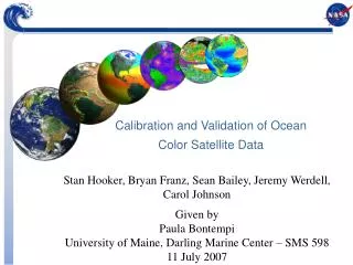
Calibration and Validation of Ocean Color Satellite Data Stan Hooker, Bryan Franz, Sean Bailey, Jeremy Werdell, Carol Johnson Given by Paula Bontempi University of Maine, Darling Marine Center – SMS 598 11 July 2007
Level 0 raw digital counts native binary format Level 1A raw digital counts HDF formatted MODIS Data Levels & Flow • ATT & EPH • spacecraft attitude • spacecraft position • GEO • geolocation • radiant path geometry • Level 1A Subset • reduced to standard ocean bands only • Level 1B • calibrated reflectances • converted telemetry • Ancillary data • wind speed • surface pressure • total ozone • Reynolds SST • Level 2 • geolocated geophysical products for each pixel
Level-2 Ocean Color Processing • Determine atmospheric and surface contributions to total radiance at TOA and subtract. • Normalize to the condition of Sun directly overhead at 1 AU and a non-attenuating atmosphere (nLw or Rrs = nLw/F0). • Apply empirical or semi-analytical algorithms to relate the spectral distribution of nLw or Rrs to geophysical quantities. • Assess quality (set flags)
What constitutes a Cal/Val Program? • Calibration/Validation is an integral component of satellite climate research missions and entails: • Prelaunch calibration and characterization • Algorithm development • Post-launch on-board and vicarious calibration • Post-launch product validation • Partnership with National Institute of Standards and Technology (NIST) provides critical personnel and equipment for prelaunch instrument calibration and characterization • Enlist partnerships with international agencies and scientists [e.g., European Space Agency (ESA)] to further enhance post-launch field validation efforts
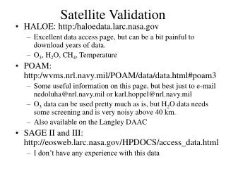
Ocean Color Calibration and Validation • A fully developed calibration and validation • program is required because… • Ocean biology and biogeochemistry products • (e.g., water-leaving radiances, chlorophyll-a) require • instrument radiometric accuracies better than 0.5%. • Climate research requires instrument radiometric • stability at the 0.1% level. A calibration/validation program for satellite ocean biogeochemistry entails multiple components, including on-orbit solar and lunar observations, modeling, ship-based observations, and long-term mooring measurements. Monthly lunar imaging is an essential component of the SeaWiFS mission and has enabled detailed tracking of sensor degradation.
Pre-Launch Calibration and Characterization Approximately 7 years from development of concept to launch, even with high Technical Readiness Levels (TRLs) Critical to understand as much of the instrument (sensor) and spacecraft performance BEFORE launch, as during launch the instrument and spacecraft behavior may change, and if they do, do you understand enough and can you fix things from the ground once on-orbit?
Calibration and Validation All things are not created equal, and calibration ≠ validation! Calibration – temporal - Lunar – detector degradation (optical bands); pitch, yaw, or roll the spacecraft so the Earth-viewing optics view the moon (SeaWiFS) or spaceport views of moon (VIIRS) - On-board – solar diffuser (MODIS) - Vicarious – the process of establishing the on-orbit instrument gain coefficients by comparing a satellite-derived radiometric quantity with the same quantity based on sea truth measurements Validation- are the results correct?
Calibration - Lunar All things are not created equal, and calibration ≠ validation! Calibration – temporal - Lunar – detector degradation (optical bands); pitch, yaw, roll the spacecraft so the Earth-viewing optics view the moon (SeaWiFS) or spaceport views of moon (VIIRS) - On-board – solar diffuser (MODIS) - Vicarious – the process of establishing the on-orbit instrument gain coefficients by comparing a satellite-derived radiometric quantity with the same quantity based on sea truth measurements
Temporal Calibration Lunar (Spacecraft roll)
Calibration – On-board Calibration – temporal - Lunar – detector degradation (optical bands); pitch, yaw, roll the spacecraft so the Earth-viewing optics view the moon (SeaWiFS) or spaceport views of moon (VIIRS) - On-board – solar diffuser (MODIS) - Vicarious – the process of establishing the on-orbit instrument gain coefficients by comparing a satellite-derived radiometric quantity with the same quantity based on sea truth measurements
Calibration – On-board/Solar Fig. 1. SDSM (Left) Outside look. (Right) Calibration schematic. SD – radiometric cal for reflected solar bands SDSM – tracks reflectances of SD, (0.4-0.9um), 2% transmission screen SRCA – track changes in radiometric cal of MODIS 0.4-2.1um, band reg BB – MWIR, LWIR, one point cal curve/detector of emissive bands SV port – zero ref point on cal curve for all 36 band EV port – format science/eng data
Calibration – On-board/Solar “MODIS bands are calibrated via the onboard solar diffuser (SD) panel, made of Spectralon. An onboard Solar Diffuser Stability Monitor (SDSM) tracks the SDs degradation. The SDSM views the sun through a 1.44% attenuation screen during SD calibration. The observed SDSM sun view response has shown serious unexpected ripples that are as large as 10% of the averaged response and consequently disable the originally designed SD degradation tracking algorithms. …a model based on geometric factors and design parameters is developed to simulate the SDSM sun view response. It is shown that the ripples are induced by erroneous design parameters and incorrect installation of the involved optical elements. The model could be used to improve the MODIS SD calibration and to provide helpful information for the design of future remote sensing systems.” (Sun et al., IEEE TRANSACTIONS ON GEOSCIENCE AND REMOTE SENSING, VOL. 43, NO. 8, AUGUST 2005)
Calibration - Vicarious Calibration – temporal - Lunar – detector degradation (optical bands); pitch, yaw, roll the spacecraft so the Earth-viewing optics view the moon (SeaWiFS) or spaceport views of moon (VIIRS) - On-board – solar diffuser (MODIS) - Vicarious – the process of establishing the on-orbit instrument gain coefficients by comparing a satellite-derived radiometric quantity with the same quantity based on sea truth measurements
Vicarious Calibration Vicarious – the process of establishing the on-orbit instrument gain coefficients by comparing a satellite-derived radiometric quantity with the same quantity based on sea truth measurements - Deep Water Calibration Site – developed late 1980’s - Marine Optical Buoy (MOBY) – site selection, time series - Other sites? - BOUSSOLE, HOT, BATS - What about the above water vs. the in-water question? - Aeronet (SeaPRISM) - Modeled - Is there promise for the future in IOOS and OOI (ORION), and do we have the sensors (characterized and calibrated) that we need?
Selection of a Deep-Water Calibration Site MOBY watch circle 1 km
Views and Maintenance of the DW Cal Site • Reference Cals • Before / After cleaning
Vicarious Calibration MOBY MOBY is used to adjust prelaunch calibration for visible bands using satellite-buoy comparisons. *Custom hyperspectral radiometers*
Lttarget TOA + Lrsat , tdsat , … Lwtarget TARGET Vicarious Calibration the operational OBPG vicarious calibration approach has (finally) been documented B.A. Franz, S.W. Bailey, P.J. Werdell, and C.R. McClain, “Sensor independent approach to the vicarious calibration of satellite ocean color radiometry,” Applied Optics (in press).
highlights: independent of sensor to be calibrated and source of ground-truth specific to Gordon and Wang (1994) describes both NIR and VIS calibration demonstrates use of MOBY for VIS calibration discusses outstanding issues and required assumptions provides (some) associated uncertainties with approach software support via SeaDAS Vicarious Calibration the operational OBPG vicarious calibration approach has (finally) been documented: B.A. Franz, S.W. Bailey, P.J. Werdell, and C.R. McClain, “Sensor independent approach to the vicarious calibration of satellite ocean color radiometry,” Applied Optics (in press).
The vicarious calibration … … makes use of a single set of fractional gains, where unity indicates no correction … (… (minimize difference between satellite Lw and ground-truth Lw)
The vicarious calibration … … makes use of a single set of fractional gains, where unity indicates no correction … (… (minimize difference between satellite Lw and ground-truth Lw) … modifies the integrated instrument-atmospheric correction system … (effectively accounts for undetermined post-launch instrument changes … (and atmospheric correction biases)
The vicarious calibration … … makes use of a single set of fractional gains, where unity indicates no correction … (… (minimize difference between satellite Lw and ground-truth Lw) … modifies the integrated instrument-atmospheric correction system … (effectively accounts for undetermined post-launch instrument changes … (and atmospheric correction biases) … assumes that temporal trends are independently removed
The vicarious calibration … … makes use of a single set of fractional gains, where unity indicates no correction … (… (minimize difference between satellite Lw and ground-truth Lw) … modifies the integrated instrument-atmospheric correction system … (effectively accounts for undetermined post-launch instrument changes … (and atmospheric correction biases) … assumes that temporal trends are independently removed … is updated periodically in data set reprocessings.
Lt(NIR) = Lr,g,wc,…(NIR) + La(NIR)+ td Lw(NIR) assumptions: (1) target sites exist where aerosol type is known (1) and Lw(NIR) is negligible (2) 865-nm perfectly calibrated, (2) such that g(865) = 1.0 implementation: knowledge of the aerosol type and La(865) permits the estimation of La(765) once La(765)target known, calculate Lt(765)target 0 M90 SATELLITE Lttarget TOA from the satellite + Lr , td , … TARGET
Vicarious Calibration – History & Frontiers • Assumptions originally made for vicarious calibration – that calibration can never equal validation • But why?
Vicarious Calibration – History & Frontiers • Tenets originally made for vicarious calibration – assumption that calibration can never equal validation • But why? • The performance of a satellite sensor must be monitored at daily to weekly intervals by comparing derived normalized water-leaving radiances with contemporaneous in situ values (both made to within the established uncertainty criteria). • Thoughts: • All methods have to comply with this requirement • 40 matchups that pass the QA criteria used in vc are needed • Needed quickly • Multiple sites or multiple investigators on ships are good, but a modeling approach will always provide the greatest number of data points in the shortest amount of time.
Vicarious Calibration – History & Frontiers • 2. The most direct way of making the in situ measurements • on a continuing daily basis over periods of several years is to utilize a specially-designed array of radiometers mounted on a moored buoy. • Thoughts: • Off-shore structures are an alternative • Is an above-water measurement more direct than an in-water measurement? • NASA’s investigators + suitable profilers = large amounts of data over time • A modeled approach is a hybrid opportunity wherein a surrogate variable (e.g., the chl a concentration; easier to measure) is used • For the in-water methods, the distinguishing aspect is the high vertical resolution of profilers versus the limited vertical resolution of a buoy (although profiling buoys are possible).
Vicarious Calibration – History & Frontiers • 3. The buoy must be designed to mount the optical collectors well away from platform shading and reflections; although, instrument self-shading corrections will be needed unless the sensors are very small. • Thoughts: • Free-fall profilers satisfy this requirement (assuming a self-shading correction is applied). • Avoid platform shading and reflections with an above-water system • and no self-shading correction is needed • A modeling approach will by definition not have any of these problems as long as the data used to initially build the model are not contaminated.
Vicarious Calibration – History & Frontiers • 4. To minimize uncertainties arising from extrapolating the upwelling radiance to the sea surface, the buoy must be moored at a location with consistently • transparent Case-1 waters and with negligible mesoscale to sub- mesoscale spatial variability. • Thoughts: • The QA criteria of the match-up process forces compliance of this requirement for all methods. • Results from BOUSSOLE, SCAPA, and SeaPRISM suggest that relaxing some of the strictness of this language (i.e., allowing the chlorophyll • concentration to rise is not significantly detrimental). • If you believe all that we know about the Case-1 model, than unequivocally clear waters are not such a strict requirement, reinforced by the model
Vicarious Calibration – History & Frontiers 5. To ensure frequent occurrences of matched satellite and buoy measurements, the site must be cloud free throughout most of the year. Thought: The QA criteria of the match-up process forces compliance of this requirement for all methods. 6. The mooring must be located close to an island-based sun photometer and sky radiance sensor to allow concurrent determinations of aerosol optical thickness and sky radiance distribution. An above-water system based on a modified sun photometer satisfies this automatically as does a modeling approach
Vicarious Calibration – History & Frontiers 7. The atmospheric conditions at the mooring location must not be significantly subjected to land-induced (e.g., orographic) effects. The QA criteria of the match-up process forces compliance of this requirement for all methods. Again, a modeling approach (ORM) satisfies this most easily. 8. Extraordinary calibration maintenance procedures are needed to ensure low uncertainties in the radiometric measurements. SIRREX (2002) http://neptune.gsfc.nasa.gov/publications/pdf/pubs2002/5_SIRREX_7_Instrumentation.pdf - showed multiple sensor designs can have similar and reproducible uncertainty budgets + the difficulty of making high-quality satellite observations does not depend on calibrations alone: buoy measurements with only a few sensors have unique problems that can be overcome using a profiling instrument or an above-water system, which measures the surface radiance field directly (just like the satellite).
Vicarious Calibration – History & Frontiers 9. Comparative shipboard measurements must be made near the buoy to check the radiometric stability of the buoy sensors, to determine spatial variability surrounding the buoy location, and to develop and validate bio-optical algorithms. All methods have to comply with this requirement. 10. The in situ radiometric measurements must reproduce the spectral response functions of the satellite sensor bands and this cannot be accomplished using commercial off the shelf (COTS) radiometers. The results from BOUSSOLE, NOMAD (plus SCAPA), and SeaPRISM all suggest this is not really true. The fight is in the field: the biggest difficulty is making high-quality measurements in the marine environment.
Vicarious Calibration – History & Frontiers 11. The need for flexibility in the choice of spectral response weighting functions used to determine band-averaged measurements imposes a requirement for full-spectrum (i.e., hyperspectral) measurements with a resolutions less than 1 nm. The results from BOUSSOLE, NOMAD (plus SCAPA), and SeaPRISM all suggest this is not really true. If hyperspectral is really needed, the ORM method can always provide this. 12. Provisions to assure radiometric stability through the extended period operations should include, as a minimum, pre- and post-deployment calibrations of all radiometers, combined with continuous monitoring of on-board light sources of known stability (if possible). All methods have to comply with this requirement. Above-water system use the sun as a calibration check or to measure a portable source (the latter can be more easily maintained, because it is not submerged). Profiling radiometers can be very easily monitored on a daily basis using a portable source.
Vicarious Calibration – History & Frontiers 13. Instruments suspended in seawater for long periods of time experience fouling by biological organisms that, if not countered effectively using anti-fouling methods and frequent cleaning by divers, seriously degrade the performance of optical sensors. Free-fall profilers do not foul, although they must be properly cared for in the field. Above-water autonomous systems experience very little fouling because the sensor is parked in a downward-viewing orientation when not in use (this could be almost completely eliminated with a movable housing guard).
Vicarious Calibration – So what do we know? There is no absolute truth. We define truth by the process or processes employed in the vicarious calibration methodology. If there are any biases in what we do, the biases will be transferred to the aircraft or satellite sensor. Given all the trade-offs between all the different possible ways of measuring a water-leaving radiance, can we use a method that is the least likely to have any inherent biases and to check that method with as many other methods as possible? Can we use above water, COTS, and models?
Vicarious Calibration Vicarious – the process of establishing the on-orbit instrument gain coefficients by comparing a satellite-derived radiometric quantity with the same quantity based on sea truth measurements - Deep Water Calibration Site – developed late 1980’s - Marine Optical Buoy (MOBY) – site selection, time series - Other sites? - BOUSSOLE, HOT, BATS - What about the above water vs. the in-water question? - Aeronet (SeaPRISM) - Modeled - Is there promise for the future in IOOS and OOI (ORION), and do we have the sensors (characterized and calibrated) that we need?
BOUSSOLE Validation, but Vicarious Calibration? http://www.obs-vlfr.fr/Boussole/ BOUSSOLE: Buoy for the acquisition of long-term optical series, but match-up of satellite-derived reflectances with in situ observations is crucial to evaluate their quality and temporal stability. BOUSSOLE: total height is 25 m. The commercial, off-the-shelf in-water radiometers (multispectral Satlantic instruments)are mounted at the end of the sensor arms which are located well above the buoyancy sphere (the largest perturbation to the light field; the underwater structure is entirely black). The above-water solar reference is sited above the solar panels, which are located 4m above the nominal seawater surface.
Validation, but Vicarious Calibration? BOUSSOLE/HOT/BATS/Aeronet/Model? - Other sites? - BOUSSOLE – coastal site – Ligurian Sea - HOT (Hawaii Ocean Time-Series): http://hahana.soest.hawaii.edu/hot/hot.html - BATS (Bermuda Atlantic Time-series Study): http://www.bbsr.edu/cintoo/bats/bats.html - What about the above water vs. the in-water question? - Aeronet (Aerosol Robotic Network, SeaPRISM): http://aeronet.gsfc.nasa.gov/ - Modeled
Validation, but Vicarious Calibration? Complementary calibration sources to support future missions Sean Bailey, Stanford Hooker, Jeremy Werdell, Bryan Franz, and David Antoine
g(443) SeaWiFS vicarious gains g(555) 40 g(765) Number Averaged figure 6 from Franz et al. (2007) MOBY has provided 1,450 contemporaneous match-ups for SeaWiFS over 9-years 150 pass the satellite screening process (approximately 17 per year) for this specific scenario … 2 to 3-years to achieve adequate sample size for reliable gain estimation using a single ground-truth target verified statistically using variance estimates and desired confidence intervals
suggested requirements for vicarious calibration sites & sources spatially homogeneous location low Ca ( < 0.2 mg m-3 ) low aerosols ( (865) < 0.15 ) hyperspectral Lwn for convolution with satellite spectral bandpass extremely well-characterized in situ radiometer limited geophysical dynamic range Clark et al. (1997), Gordon (1998), Clark et al. (2003)
preliminary results … standard exclusion criteria applied to MOBY, NOMAD, and SCAPA Ca restriction increased to 0.3 mg m-3 for BOUSSOLE Ca restriction increased to 2 mg m-3 for AERONET-OC, which includes AAOT, COVE, and MVCO sites
STD AERONET-OC BOUSSOLE MOBY NOMAD ORM (B+H) SCAPA std dev (avg) 0.025 0.010 0.009 0.012 0.014 0.014 preliminary results … data from 3 sites no 510-nm non-zero NIR low sample size evaluation metrics TBD (define “truth”) spectral shape reproduced by all sources, magnitudes vary sensitivity of requirements TBD
preliminary results … gains recalculated with N = 17 N increased by relaxing exclusion criteria Ca restriction increased to 0.5 mg m-3 #-valid-pixels restriction reduced to 13 ratio of N=19 to N=50 from left figure
Vicarious Calibration Vicarious – the process of establishing the on-orbit instrument gain coefficients by comparing a satellite-derived radiometric quantity with the same quantity based on sea truth measurements - Deep Water Calibration Site – developed late 1980’s - Marine Optical Buoy (MOBY) – site selection, time series - Other sites? - BOUSSOLE, HOT, BATS - What about the above water vs. the in-water question? - Aeronet (SeaPRISM) - Modeled - Is there promise for the future in IOOS and OOI (ORION), and do we have the sensors (characterized and calibrated) that we need?
Available In Situ Match-Ups by Mission SeaWiFSSept 1997 - Present MODIS/AquaJuly 2002 - Present
Comparison of Water-Leaving Radiances to In Situ MODIS/Aqua SeaWiFS
Comparison of Chlorophyll Retrievals to In Situ MODIS/Aqua SeaWiFS