Download
1 / 37
370 likes | 616 Views
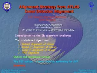
Alignment Strategy from ATLAS Inner Detector Alignment. LHC Detector Alignment Workshop CERN 05/09/06. Pawel Br ü ckman de Renstrom p.bruckman@physics.ox.ac.uk On behalf of the ATLAS ID alignment community. Introduction to the ID alignment challenge. The track-based algorithms:.

E N D
Alignment Strategy from ATLASInner Detector Alignment LHC Detector Alignment Workshop CERN 05/09/06 Pawel Brückman de Renstromp.bruckman@physics.ox.ac.ukOn behalf of the ATLAS ID alignment community Introduction to the ID alignment challenge The track-based algorithms: • Robust Alignment of silicon • Global 2Alignment of silicon • Local 2Alignment of silicon • TRT alignment Optical and mechanical surveys The FSI system – a novel stability monitoring for SCT Summary
The alignment strategy PIXEL + SCT: very high granularity silicon system (~6000 modules) TRT: proportional straw tubes – for alignment purpose granularity limited to barrel modules/end-cap disks (96+28) TRT needs intrinsic calibration (RT with some coarse granularity, T0 at single straw level) – see later TRT 96 barrel modules 2x14 end-cap disks • Current strategy: • Perform full intrinsic alignment of the silicon • Align TRT modules using tracks from silicon • Alternative (under consideration): • Do a combined simultaneous alignment of both subsystems • TRT helps to constrain momentum, • alignment algorithms have same problems (convergence, unconstrained degrees of freedom, etc), • allows for implementing a single pass algorithm - highly recommended for “fast response”. For more details on the ID subsystems see yesterday talk from Florian Bauer
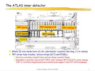
Barrel SCT (4 layers) Forward SCT (9 disks) Forward PIXels (3 disks) Barrel PIXels (3 layers) ATLAS Silicon Tracking System 3 translations & 3 rotations of each module In total we have to deal with 34,992 DoF’s!
y x z 2004 Combined Test Beam • First ever real data from all three subsystems! • Abundant statistics at different beam momenta (2-180 GeV) (O(105) tracks/module/energy), • Magnetic field. Followed by 6 TRT modules 8 SCT modules 6 PIXEL modules • A very small setup (14+6), • Layout creating ildefined modes (collimated beam through a narrow tower of modules)
ID is taking shape! Barrel TRT SR1 surface building (spring 2006) Barrel SCT service cages visible
View from outside towards Side A June 2006 SR1 Cosmic Run(nearly 400k cosmic events recorded) • SCT: • 468 of 2112 modules ~ 1/4 of SCT barrel • TRT: • 2X ~6600 Channels ~ 1/8 of TRT barrel • 3 scintilators for trigger • No PIXEL, No B-field! • Low p tracks dominate:
Slides from Florian Heinemann Robust Alignment • Algorithm uses • PIXEL and SCT detector description • Mean residuals • Mean overlap residuals • Alignment of neighbouring modules Tracks in StoreGate Digits Reconstruction RobustAlignAlg Stable, no minimisation required Covers mainly 2 - 3 out of 6 DoFs for each module Alignment Constants Iteration until convergence Final Alignment Constants Responsible: Florian Heinemann (f.heinemann1@physics.ox.ac.uk)
Slides from Florian Heinemann CTB Alignment PIXEL Convergence after 15 iterations Before alignment After alignment Residuals & Overlap Residuals - Mean & RMS SCT Iteration
Slides from Florian Heinemann Cosmics Alignment Preliminary After 8 iterations: RMS 61µm → 47µm After 8 iterations: RMS 81µm → 69µm
track Intrinsic measurement error + MCS hit residual Key relation! Direct Least-Squares solution to the alignment problem The method consists of minimizing the giant 2resulting from a simultaneous fit of all particle trajectories and alignment parameters: [ATL-INDET-PUB-2005-002] Let us consequently use the linear expansion (we assume all second order derivatives are negligible). The track fit is solved by: while the alignment parameters are given by: Equivalent to Millepede approach from V. Blobel
“Weak modes” - examples “clocking” R (VTX constraint) radial distortions (various) “telescope” z~R • dependent sagitta • XabRcR2 • We need extra handles in order to tackle these. Candidates: • Requirement of a common vertex for a group of tracks (VTX constraint), • Constraints on track parameters or vertex position (external tracking (TRT, Muons?), calorimetery, resonant mass, etc.) • Cosmic events, • External constraints on alignment parameters (hardware systems, mechanical constraints, etc). • [PHYSTAT’05 proceedings] & talk from Tobi Golling • dependent sagitta “Global twist” • Rcot() global sagitta R …
Example “lowest modes” in PIX+SCT as reconstructed by the 2algorithm Global Freedom have been ignored (only one Z slice shown) • The above “weak modes” contribute to the lowest part of the eigen-spectrum. Consequently they dominate the overall error on the alignment parameters. • More importantly, these deformations lead directly to biases on physics (systematic effects).
=10.7 μm =19.1 μm CTB: convergence of the Global Chi2 algorithm PIX SCT Before alignment After alignment
SR1 cosmics with Global Chi2 very preliminary (~250k tracks) Corrections due to modes >1500 first iteration x100 Alignment corrections for rigid barrels =46 μm =32 μm TX TY TZ RX RY RZ [mm] [mm] [mm] [mrad] [mrad] [mrad] Barrel3 -0.0044 -0.0162 -0.0169 0.0685 -0.0185 0.0503 Barrel4 0.0061 0.0329 -0.0462 -0.0678 0.0258 0.0527 Barrel5 0.0109 -0.0005 0.0865 0.0318 -0.0134 -0.0947 Barrel6 -0.0126 -0.0162 -0.0234 -0.0200 0.0073 -0.0083 Indication of very good assembly precision!
Full Barrel Geometry with Global Chi2 alignment Full barrel i.e. 21408 DoF’s (11.5.0, iPatRec, no VTX) Nominal geometry - no misalignments: Pulls of all corrections of ~unit width and centred at zero pdsyevd of ScaLAPACK on a ||-cluster AMD Opteron (64-bit). Using 16 CPU grid N=21k system diagonalised within ~1h! [CHEP’06 proceedings] 32 nodes should solve the full 35k in <3h. =0.94 Pulls in diagonal base Pulls of alignment corrections Alternative options as suggested by V. Blobel under investigation!
Slides from Roland Haertel Local 2 alignment - approach • Size of the matrix for full ATLAS 2 problem is 36k x 36k. Reduce this by looking only at 6x6 block matrices at the diagonal of the full size matrix. This neglects all inter-module correlations: • Approximation is valid if tracking uncertainty is smaller than measurement uncertainty. • No bias corrections. Unbiased residuals and track parameters used. • Diagonal covariance matrix is assumed, i.e. correlated errors from MCS are neglected. • Inter-module correlations are there and cannot simply be ignored. Correlations are treated by iterating the procedure.
Slides from Roland Haertel Local 2 alignment - functionality • Algorithm tested with combined testbeam, cosmic test and full ATLAS geometry setup. • Alignment accuracy achievable for the precision coordinate with O(100k) tracks for full ATLAS setup, starting from nominal alignment: Pixel barrel 10 m, Pixel endcap 2 m, SCT barrel 50 m, SCT endcap 20 m. • Simulation samples with systematically deformed detector geometry are being produced. Validation test with these samples will follow • Simple implementation, additional features are already implemented (survey constraints, global alignment) or will be implemented soon (Kalman style approach, overlap constraint, vertex constraint). Pixel barrel alignment parameter ax distribution and flow for full ATLAS setup:
Slides from Roland Haertel Local 2 alignment – cosmic performance • Alignment of SCT barrel cosmic test setup with 24k tracks. No B-field and no momentum selection. • Alignment correction scaling parameter (0.5) used to dampen oscillations. flow of alignment parameter ax for all modules of barrel layer 2 through the iterations development of width and mean of residual distributions through the iterations
TRT alignment • Based on local chi2 principle using reference tracks from the silicon • Can determine up to 5 DoF per individual module (two translations and three rotations) • TRT is an assembly of gas chambers – internal calibration needed (RT, T0) cosmics run 2267 >10ns cosmics run 2267 worst module
TRT alignment - CTB • Followed the alignment of silicon • Could accurately detect time dependent movements of TRT vs silicon: Relative TRT shift in sensitive direction (left) and rotation (right) as a function of the run number (time):
Δphi0 Δrphi TRT alignment – SR1 Cosmics(preliminary study) • Intrinsic residuals for TRT-only tracks indicates very good assembly precision • Matching between track segments from SCT and TRT provides a measure of the global misalignment between the two systems: • no large global rotation in XY plane (error large: MS can hide effect) • large (~0.5mm) misalignment in Rphi • about 0.2 mrad rotation in the XZ plane.
Slides from Muge Unel SCT photogrammetry in SR1 SCT Barrel photogrammetry survey in SR1 has been completed early this year. SCT-TRT relative position survey also performed.
Slides from Muge Unel Interlinks: Deformations? • Measurements performed before and after insertion into TRT. Detailed measurements exist before the insertion O(20μm) in XY. • After insertion only coordinate system transfer was measured. • The individual cylinder interlink data showed deformations consistent with tilted ellipses. • Face A and face C appear to be rotated in opposite directions, hinting at twists of the complete barrel. • Relative clocking of barrels preliminarily confirmed with cosmics! B3 B4 B5 B6 Circles (colored) are fits, black curves are guidelines for ellipses using the scaled up differences of data points (col) to the circles
Slides from Tobi Golling Mean: -2.5 µm Sigma: 2.7 µm Mean: -0.2 µm Sigma: 2.6 µm Survey Constraint on Alignment ATL-INDET-PUB-2006-001 Module survey in Pixel Endcap Delta X = Xmeasured - Xnominal Delta Y = Ymeasured - Ynominal Survey constraint based on: • CMM survey of Pixel and SCT prior to installation • Estimated uncertainties Systematics (thermal expansion, moisture) dominate.
Slides from Tobi Golling Survey Constraint on Alignment • Survey data describes test module's position wrt reference modules • No constraint on modules' absolute positions is imposed Step 1: • Find global transformation of reference modules from survey alignment to current alignment, in other words: Minimize the distance between the survey measurement points (unbiased) ⇒ Prediction of test module's position Step 2: Transformation of test module from current position to predicted position from survey represents alignment correction Reference modules Test Reference modules (Current alignment) Test Step 1 Step 2 Test (Survey alignment) Test Reference modules
Slides from Stephen Gibson End-cap SCT 842 simultaneous length measurements in SCT! Barrel SCT End-cap SCT 165 165 80+(3x[80+16])+(2x72)=512 END FLANGES B3 B4,5,6 FrequencyScanningInterferometry • Runtime alignment system monitors shape changes of the SCT. • Provides access to short-timescale and low spatial frequency modes of tracker distortion (e.g. sagitta). • On-detector system forms a geodetic grid of length measurements between nodes attached to the SCT support structure. • All 842 grid line lengths are measured simultaneously to a precision of <1micron. • Entire Grid shape can be determined to better than 10m in 3D.
Slides from Stephen Gibson Barrel FSI FSI grid nodes attached to inner surface of SCT carbon-fibre cylinder
Slides from Stephen Gibson Barrel FSI Distance measurements between grid nodes precise to <1 micron
Slides from Stephen Gibson End-cap FSI (1/18)
Slides from Stephen Gibson Time FSI months Tracks days hours minutes seconds Spatial frequency eigenmode FSI: integration with track alignment • Time + spatial frequency sensitivity of FSI complements track based alignment: • Track alignment seeks average alignment over interval t0-t1 = 24hrs+. Good for high spatial frequency eigenmodes, “long” timescales. • FSI provides “short” timescale (~10minutes) movement field for low spatial frequency eigenmodes. • Need both to achieve best alignment. • How to include time dependency? • FSI provides low spatial frequency module corrections at time ti , t0<ti<t1 • Track recorded at time ti is reconstructed using FSI module correction at time ti . • Offline alignment uses FSI corrected tracks to solve for high spatial frequency modes, averaged over t0<ti<t1, low frequency modes frozen. • Subsequent reconstruction of track at time tj uses average alignment from a track-based algorithm + time dependent FSI module correction, tj, t0<tj<t1
Summary • ID of ATLAS adopted variety of techniques in order to assure optimal alignment of its precision tracking devices. • There are three independent track-based alignment algorithms for silicon, a complementary TRT alignment, a common approach to survey constraints and a novel Frequency Scanning Interferometry system in the SCT. • All track-based algorithms have provided convincing proof of principle. Full-scale tests using large simulation samples are due later this year. • Preliminary burn-in of the algorithms assure by the 2004 CTB. • Alignment of the real detector is already a reality! We have collected ~400k cosmic events in the SR1 building with SCT+TRT detectors. Very high assembly precision has been confirmed. PIXEL detector will take surface cosmics separately and will be inserted into the ID in the pit. • FSI is getting ready to monitor SCT distortions during the PIXEL insertion process (detect shape difference before and after insertion). • This will be followed by pit cosmics and ultimately accelerator events.
Slides from Florian Heinemann Alignment Constants Sum over neighbours, take correlations into account Sum over all modules in a ring Correct for change in radius For a perfect detector:
New key relations! Direct Least-Squares solution to the alignment problem (2) Fitting a common vertex for a group of tracks We follow the same principle but now we have Individual track parameters are reduced to while tracks from the same vertex share the same set of three parameters describing the common vertex position. where Using the new form of the full derivative we obtain solution for the alignment parameters: were we have defined:
Slides from Stephen Gibson Ratio of phase change = Ratio of lengths DJ = [2p/c]LDn DF = [2p/c]DDn
Slides from Stephen Gibson Return Fibre Fused Silica Delivery Beam-splitter Fibre Quill components Distance measured Retroreflector FSI – Grid Line Interferometer
Slides from Stephen Gibson FSI barrel-flange component (1/48)