Download
1 / 43
430 likes | 629 Views
Lessons from the ATLAS SCT alignment system for LC detector and MDI alignment. and new technology developments. Armin Reichold for the AMULET collaboration. Overview. ATLAS SCT online FSI alignment (60%) Purpose and Requirements How it works How it was meant to be used

E N D
Lessons from the ATLAS SCT alignment system for LC detector and MDI alignment and new technology developments Armin Reichold for the AMULET collaboration LC-2013 Armin Reichold
Overview • ATLAS SCT online FSI alignment (60%) • Purpose and Requirements • How it works • How it was meant to be used • How the SCT performed • How it is actually used • Improvements in FSI technology (30%) • Dynamic FSI • Commercial availability • Conceptual LC alignment applications & conclusions (10%) LC-2013 Armin Reichold
Disclaimer • I am not a member of the ATLAS collaboration (any more) • I WAS involved in building the online FSI alignment system for the SCT • Now working on new FSI technology • Conclusions concerning ATLAS arise from contact with colleagues (R. Nickerson, S. Gibson, P. Coe), discussions and papers (see list at end of talk) • ATLAS alignment pictures and graphs largely from: ## = “Rapid precise shape monitoring of the ATLAS silicon tracker”, S. Gibson, see Bibliography LC-2013 Armin Reichold
~7m ATLAS SCT online alignment system • Purpose: • Follow changes of tracking detector shape which are too fast to catch with track-based alignment • These were expected due to heat load variations from trigger rate changes and other sources • Correct detector positions during such changes • Statistical misalignment of tracker elements should not increase statistical error on track parameters by more than 20% at any time • Constrain deformation modes that are “weakly” measured by track alignment ## LC-2013 Armin Reichold
ATLAS SCT online alignment system • Resolution requirements • ATLAS tracker resolutions are moderate compared to LC plans • ATLAS Pixels: σr*φ = 10 µm , σz = 115 µm (LC: 4-7 µm) • ATLAS Strips: σr*φ = 17 µm (LC: 12 µm) • Demands on alignment accuracies for ATLAS: • Pixels: σalign-r*φ = 7 µm • Strips: σalign-r*φ = 12 µm LC-2013 Armin Reichold
Examples of weakly constrained modes Some types of distortions can leave the tracks helical, but systematically biased “clocking” R (VTX constraint) radial distortions (various) “telescope” z~R • dependent sagitta XabRcR2 Theseneed extra handles to measure such as: • Common vertex for a group of tracks (VTX constraint), • Constraints on track parameters or vertex position (external tracking (TRT, Muons), calorimetery, resonance mass, etc.) • Cosmic events (not from vertex) • External measurements of alignment parameters (hardware alignment systems, mechanical constraints, etc). [PHYSTAT’05 proceedings] • dependent sagitta “Global twist” Rcot() global sagitta R … Stephen Gibson et al
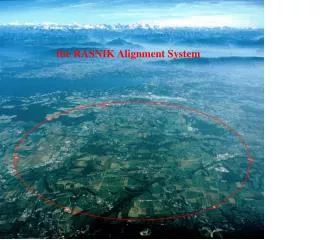
ATLAS SCT online alignment system • How it works • Geodetic grid of length between nodes on support structure • Frequency Scanning Interferometry (FSI) designed to measure 842 lengths relative to stable reference interferometer • Monitor support structure NOT sensors (too many DOF=34,992) • Lengths measured “simultaneously” to a precision of < 1µm. • Repeat every 10 min. to track deflections End-cap SCT grid (165) End-cap SCT grid (165) Barrel SCT grid (512) LC-2013 Armin Reichold
TUNABLE LASER sweep n Very Basic Principle of FSI DETECTOR M1 M2 To interferometer with length to be measured Reference Interferometer with fixed length IMEASURED IREF n2 n2 n1 n1 n n DJ = [2p/c]DDn DF = [2p/c]LDn Ratio of phase change = Ratio of lengths Stephen Gibson et al
ATLAS SCT online alignment system: System Overview Underground read-out rack ATLAS detector Laser room above ground Stephen Gibson et al
Tuneable laser amplifier system Stephen Gibson et al
ATLAS SCT online alignment system • Front-end components of • minimal mass • high radiation tolerance LC-2013 Armin Reichold
ATLAS SCT online alignment system ## FSI grid nodes attached to inner surface of SCT carbon-fibre cylinder LC-2013 Armin Reichold
ATLAS SCT online alignment systemHow it was meant to be used • Determineapproximate FSI network geometry via: • Design positions • Photogrammetry of end views (64 markers, 20 microns transverse accuracy) • Quasi-geodetic grid needs assumptions to solve study structure deflections (FEA, ESPI deflection measurements) • Relate FSI grid shape todetector module positions • x-ray survey cancelled • FSI monitors support shape changes • assume low order deflections (low spatial frequencies) of support from FEA • translate these into module position corrections • Combine • FSI module correction every 10 min • track alignment of high order deflections (excluding low orders). LC-2013 Armin Reichold
ATLAS SCT online alignment system B=2 Tesla • But …. • SCT is super stable: • stdev ~25 nm over2 hours before and after solenoid ramp • stdev < 50nm over 24 hours • Only few barrel interferometers shown B=0 Tesla LC-2013 Armin Reichold
ATLAS SCT online alignment system • And very repeatable • after solenoid ramp • return to start values to stdev ≈49nm around old values • only few barrel lines shown • Therefore LC-2013 Armin Reichold
ATLAS SCT online alignment systemHow it is actuallyused • FSI distortion measurements not needed during regular operation (detector too stable) • Alignment done by tracks alone (no FSI corrections) • FSI determines periods of stability for track alignment • What alignment people would have liked instead: • FSI system more optimised to measure “weak modes” • ATLAS upgrade tracker will be planned with this in mind LC-2013 Armin Reichold
ATLAS SCT online alignment system • By now this is “old” technology • lasers: λ=835nm (not telecoms) • Slow mode hop free tuning • small tuning range • external beam splitters • metalreflectors • two fibres for each line • reference interferometer defines the length scale • but this has improved … LC-2013 Armin Reichold
New FSI technology • FSI development continued after ATLAS • Initially work aimed at LC applications • LiCAS= ILC main linacalignment • AMULET = FF stabilisation • Ended abruptly when STFC withdrew UK support for ILC • Later work aimed at commercialisation • Projects: AMULET, Comet • new funding via EPSRC, ETALON AG, NPL • Aims: • Measure absolute length in meters traceable to SI definition • Measure varying length L(t) not only tolerate changes and average • Higher measurement frequency • Lower cost • Improve practicability (speed, analysis, handling, etc.) • Make it into a toolkit for metrology applications LC-2013 Armin Reichold
Dynamic FSI: Schematic (Patented) LC-2013 Armin Reichold
Dynamic FSI: hardware changes • Moved to telecoms wavelength 1550nm • wide tuning range O(100nm) • fast tuning O(1000nm/s) • cheap lasers and other components • cheap extra power due to EDFA • Easier to be eye safe • Both lasers present in all interferometers simultaneously (no multiplexing or chopping) • Gas absorption cells provide length scale via physically fixed absorption features • naturally long term stable • minimal influence from environment (pressure shifts) • traceable to SI meter via frequency comparison • much cheaper & simpler than invar reference • Fibre reference interferometers • stability required over O(1 sec) • length measured each “shot” • compact, cheap, coiled fibre interferometer • Single fibre for delivery and readout • No external beam splitter (fibre end = beam splitter) • Use collimated beams up to 50m Long arm reflection from retro reflector Short arm reflection from fibre tip inside collimator LC-2013 Armin Reichold
Dynamic FSI: new capabilities • Measure changing (< 19 mm/s) ABSOLUTE distances time resolved at 2.77 MHz inside each scan • Scan resolution better than ± 0.1μm • Scan repetition rates 0.1 to 10 Hz • Absolute measurement uncertainty <±0.5 μm/m (at 95% CL) over life time LC-2013 Armin Reichold
Dynamic FSI: verification 0.2 to 20m measurement noise truly random average many measurements to improve resolution if target is stable 464pm= 188nm= LC-2013 Armin Reichold
Dynamic FSI: Measurement Results with commercial Multiline™ system • One line monitor piezo-driven vibrating target 60 cm away • One line monitors linear motion of target on stepper motor stage 75-90 cm away 5.5 μm @ 300 Hz 150 mm @ <=18 mm/s A Novel Multichannel Interferometer System For Measuring Absolute Distances
Monitoring of a vibrating target 5.5 μm 300 Hz 600 Hz 900 Hz A Novel Multichannel Interferometer System For Measuring Absolute Distances
Monitoring of a slowly moving target Velocity = 18 mm/s 150 mm 1 mm 1 μm A Novel Multichannel Interferometer System For Measuring Absolute Distances
Dynamic FSI: Commercial Multiline™ system from ATAON AGwww.etalon-ag.com/index.php/en /products/multiline • 24 measurement lines • Up to 88 lines with extra DAQ cards in current DAQ crate • Laser system can power up to 200 lines • With EDFA practically no limit on number of lines • Extra DAQ crates attached via USB • Fully calibrated and traceable • Entire system in single “small” rack • CERN and SLAC will buy Multiline System in development rack smaller rack smaller rack Courtesy of ETALON-AG LC-2013 Armin Reichold
What do we need to align for LC • Track and Vertex detectors • Higher resolution compared to ATLAS wants better alignment • Lower mass (LC vertex det = few 0.1% X0, ATLAS pixels few % X0) will make distortions bigger • Push-Pull makes distortions more frequent and likely • tracker needs to be aligned to other non-tracking detectors as well (cannot be done with track alignment) • Entire detector needs to be aligned to beam line after push pull • MDI elements • hard to reach inside detector • Push pull will move them around • see next slide for some concepts LC-2013 Armin Reichold
(CLIC solution for FF pre-alignment from Lau Gatignon’s talk, Tue. am) Harry van der Graaf / NIKHEF • replace zeroduresokeswith FSI lines • lines of sight as long as you like may go entirely outside detector • no mass no vibration fed into quadrupoles • minimal cross-section easier integration • augment Rasnikwith FSI • see motion of spoke ends • if space found on outside: • extend to FSI network • connect network to outside world (beamline, detector) LC-2013 Armin Reichold
(CLIC solution for QD0 pre-alignment from Lau Gatignon’s talk, Tue. am) no need for ring FSI markers can go directly onto quadrupole LC-2013 Armin Reichold
Conclusions • FSI technology matured and commercially available • FSI can be a powerful tool for various alignment systems • It is Pointless to hardware align DOF that either: • are readily determined by track alignment must know track alignment capabilities • or do not vary significantly during operation design of hardware alignment is also integral to design of support structure • Weak modes can eventually be aligned with tracks but: • needs special constraints (invariant masses, common vertex, external tracking, calorimetry, cosmics) • therefore takes a lot of data over a long time • hardware alignment can track weak modes over long times and enable track alignment data to be used over long times • Hardware and track alignment must be designed together with tracking mechanics • ATLAS upgrade projects are now starting to go through this process • ATLAS expertise grown over first run is “available and willing to help” • Sorry: All LC alignment specific technical work unfunded in UK • But: There is hope and there is interest;@) LC-2013 Armin Reichold
Thanks to • The AMULET collaboration: • John Dale1, Ben Hughes2, Andrew Lancaster3, Andrew Lewis2, Armin Reichold3, Heinrich Schwenke4, Matt Warden1 1: DESY, 2:NPL, 3:Oxford JAI, 4:ETALON AG • The ATLAS SCT alignment team • The audience for all that patience LC-2013 Armin Reichold
Backup Slides and repeats for PDF prints LC-2013 Armin Reichold
Bibliography of ATLAS stuff • Rapid precise shape monitoring of the ATLAS silicon tracker. S. Gibson • http://indico.cern.ch/materialDisplay.py?contribId=29&sessionId=1&materialId=slides&confId=13681 • Alignment of the ATLAS Inner Detector Tracking System with 2010 LHC proton-proton collisions at √s = 7 TeV • ATLAS-CONF-2011-012 • First data from the ATLAS Inner Detector FSI Alignment System • http://www-conf.kek.jp/past/iwaa08/papers/FR002.pdf • http://www-conf.kek.jp/past/iwaa08/presents/FR002_talk.pdf • Study of alignment-related systematic effects on the ATLAS Inner Detector track reconstruction, • http://inspirehep.net/record/1204342/files/ATLAS-CONF-2012-141.pdf • A NOVEL METHOD FOR ATLAS FSI ALIGNMENT BASED ON RAPID, DIRECT PHASE MONITORING, • http://cds.cern.ch/record/1305878/files/ATL-INDET-PROC-2010-037.pdf • http://cds.cern.ch/record/1291618/files/ LC-2013 Armin Reichold
Dynamic FSI: Commercial Multiline™ system from ATAON AGwww.etalon-ag.com/index.php/en /products/multiline • 24 measurement lines • Up to 88 lines with extra DAQ cards in current DAQ crate • Laser system can power up to 200 lines • Extra DAQ crates attached via USB • With EDFA practically no limit on number of lines • Fully calibrated and traceable • Entire system in single small rack • CERN and SLAC will buy Courtesy of ETALON-AG LC-2013 Armin Reichold
What do we need to align for LC • A word on FF stabilisation • Continuous dynamic FSI exists (thesis A. Lancaster) • Higher resolutions are coming available (thesis A. Lancaster) • Combinations with classical interferometry are being tested nm resolutions are the aim • Sorry: All LC alignment specific technical work currently unfunded • But: There is hope and there is interest ;@) LC-2013 Armin Reichold
End-cap FSI (1/18) ## LC-2013 Armin Reichold
ATLAS SCT online alignment system • ATLAS FSI operation methods • “Absolute mode”: • Measure OPD ratio of unknown interferometer to stabilised, evacuated reference interferometer • one length measurement every frequency scan O(once per 8 minutes) • sub-micron sensitivity (varies with signal to noise) • “Vibrato mode”: • Relative change of measurement interferometer length • Once every 8 seconds • 50nm sensitivity LC-2013 Armin Reichold
Two colour laser amplifier system Stephen Gibson et al
Two colour laser amplifier system Stephen Gibson et al